Modbus Data Base
Publication PUB091-003-00_0119
51 of 76
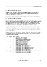
7.6.5
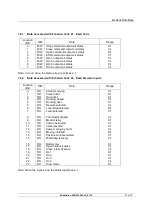
Data Accessed with Function Code 05 and 15 – Force Single and Multiple Coils
Location
(Bit)
R/W
Data
Range
0
R/W
Stop command output coil status
0-FF00 hex
1
R/W
Close command output coil status
0-FF00 hex
2
R/W
Open command output coil status
0-FF00 hex
3
R/W
ESD command output coil status
0-FF00 hex
4
R/W
DO-1 output coil status
0-FF00 hex
5
R/W
DO-2 output coil status
0-FF00 hex
6
R/W
DO-3 output coil status
0-FF00 hex
7
R/W
DO-4 output coil status
0-FF00 hex
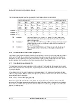
Using code 05 write FF00 (hex) to turn on the command, DO-1 to DO-4 are turned off by writing ‘0’.
The other coil commands are cleared by various means as explained in Section 5.1.2.
Using code 15 write 1 to turn on the command and 0 to turn off the command.
The commands to open, close, stop or ESD the actuator are not cancelled by writing a ‘0’. The
actuator latches the instruction and will complete the action unless a subsequent counter command is
received before the action is completed.
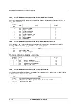
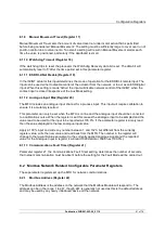
7.6.6
Data Accessed with Function Code 06 and 16 – Preset Single and Multiple Registers
Location
(Reg/Bit)
R/W
Data
Range
5
-
R/W
Actuator Digital Control
0-3
0 = stop,
1 = close
2 = open
3 = ESD
6
-
R/W
Actuator Position DV (desired value)
0-3E8 hex
(0.0 – 100.0%)
The Actuator Digital Control register allows one of the four commands to be selected by writing the
appropriate value.
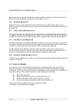
Provided limited range positioning is not invoked, the Actuator Position DV register assigns a special
importance to the values 0% and 100% written to this register. The command is revised so as to fully
close the valve to its tight shut off position (0%) and fully open the valve (100%).


