


2200
16
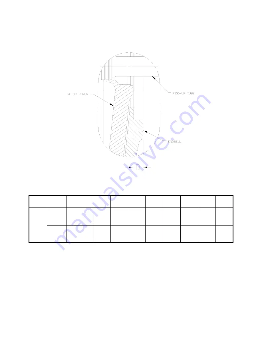
2.5. SEAL
SHIMMING
Figure 2-10: 2-7/8” Type S Single Seal Shimming Diagram
Table 2-7: Type S Single Seal Shimming Chart
Number of
Shims Required
Required
Setting
1
2
3
4
5
6
7
8
B
Inches
0.818
---
0.804
0.833
---
0.819
0.848
---
0.834
0.863
---
0.849
0.878
---
0.864
0.893
---
0.879
0.908
---
0.894
0.923
---
0.909
0.938
---
0.924
mm
20.77
---
20.42
21.16
---
20.80
21.54
---
21.18
21.92
---
21.56
22.3
---
21.95
22.68
---
22.33
23.06
---
22.71
23.44
---
23.09
23.83
---
23.47
NOTE:
For proper bearing and seal location, dimension “B” (as
shown in Figure 2-10
)
must be controlled. Use the shimming bar (P/N 060580635) and a depth
micrometer to measure the seal height.
The seal height measurement is then subtracted from the number stamped on the
measuring bar. This will give you dimension “B”. Referring to the shim chart and
the box in which the measured value “B” falls. (The shimming chart is based on
shims .015” thick, actual thickness may vary.)
Содержание 2200
Страница 8: ...2200 5 2 2 DIMENSIONAL DRAWINGS Figure 2 2 2200 2x2 Dimensional Drawing ...
Страница 9: ...2200 6 Figure 2 3 2200 3x2 Dimensional Drawing Threaded ...
Страница 10: ...2200 7 Figure 2 4 2200 3x2 Dimensional Drawing Flanged ...
Страница 15: ...2200 12 Figure 2 7 2200 Rotor Assembly Section Drawing ...
Страница 36: ...2200 33 9 MAINTENANCE RECORD DATE SERIAL NO MAINTENANCE RECORD BY ...
Страница 40: ...2200 37 Figure B 2 Alignment Tool Location 3x2 Pump ...