background image

4801-5164J

20 October 2021

57

RS-500 5K Walk-In Cooler Door Installation and Operation Manual

   WARNING/AVERTISSEMENT

The door assembly contains dangerous rotating machinery! Keep hands, clothing, 

etc.

 clear during operation. Do not operate 

the door unless all guards and covers are in place.

Le système contient des machines tournantes dangereuses! Gardez les mains, les vêtements, etc. dégagés pendant le 

fonctionnement. N'utilisez pas la porte tant que tous les protecteurs et couvercles ne sont pas en place.

   WARNING/AVERTISSEMENT

The installer is responsible for complying with all relevant regulations (

e.g.

 wiring and accident prevention). Particular attention 

must be paid to the cross-sectional areas of conductors, the selection of fuses and other electrical protection, and the use of 

protective ground/earth connections.

L'installateur est responsable du respect de toutes les réglementations en vigueur (par ex. câblage et prévention des accidents). 

Une attention particulière doit être portée aux sections transversales des conducteurs, à la sélection des fusibles et autres 

protections électriques, et à l'utilisation de connexions de protection terre.

   PROPOSITION 65 WARNING

California Proposition 65 Warning: This product can expose you to chemicals, including lead, which is known to the State of 

California to cause cancer or birth defects or other reproductive harm. 


For more information, go to 

www.p65warnings.ca.gov/furniture

.

   WARNING/AVERTISSEMENT

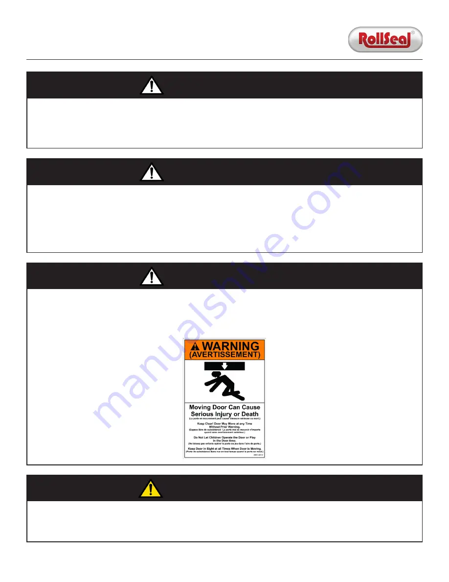
Two copies of item 4501-6312 (Moving Door Warning Label) are supplied with the door. One must be applied inside the door 

opening. The other must be applied outside the door opening.

Deux exemplaires de l'article 4501-6312 (étiquette d'avertissement de mouvement de porte) sont fournis avec la porte. Un doit 

être appliqué à l'intérieur de l'ouverture de la porte. L'autre doit être appliqué à l'extérieur de l'ouverture de la porte.

Содержание RS-500 5K

Страница 1: ...4801 5164J 20 October 2021 RS 500 5K Walk In Cooler Door Installation and Operation Manual 1...

Страница 2: ...hes and Smart Controller Section 3 1 2 Auxiliary Devices Section 3 2 Egress Track System Section 3 3 Home and Auxiliary Safety Sensors Leading Edge Switch Section 3 4 Infrared Safety Beam Section 3 5...

Страница 3: ...s Section 6 1 Switch Card and Safety Beams Section 6 2 Head Unit Section 6 3 Remote Receiver Section 7 Accessories Section 7 1 Passive Infrared Motion Sensor Section 7 2 Wave Close Proximity Sensor Se...

Страница 4: ...al Section 1 Introduction NOTICE This document is subject to change without notice The latest version is maintained at rollseal net rollseal technicals This manual describes the following aspects of t...

Страница 5: ...tampered with by unqualified personnel b any of the Product s component parts have been replaced by anything other than authorized RollSeal replacement parts c the Product has been modified in any way...

Страница 6: ...us applications including cold storage and environmental rooms RS 500 WIC doors are manufactured up to 6 W x 9 H have a maximum speed of 27 per second and are suitable for foot and pallet jack traffic...

Страница 7: ...3A at 115VAC Single Phase or 1 5A at 230VAC Single Phase Standby Power 0 2A at 115VAC Single Phase or 0 1A at 230VAC Single Phase Speed Up to 27 per Second Horsepower 1 6 HP Features Soft Start Stop E...

Страница 8: ...speeds of the door count the number of door cycles and provide status information for remotely monitoring the door s position Furthermore the Smart Controller can incorporate several auxiliary device...

Страница 9: ...4801 5164J 20 October 2021 9 RS 500 5K Walk In Cooler Door Installation and Operation Manual Section 1 5 Dimensions...

Страница 10: ...r Opening 1 Using the diagram on the following page determine the required dimensions of the clear opening If necessary adjust the dimensions of the mounting posts and or framing members to suit the n...

Страница 11: ...4 8 85 7 8 91 3 8 96 7 8 102 4 8 108 1 8 113 7 8 3 5 W 83 3 8 88 5 8 93 7 8 99 3 8 104 6 8 110 2 8 115 7 8 4 W 86 4 8 91 5 8 96 6 8 102 107 3 8 112 6 8 118 1 8 4 5 W 90 94 7 8 99 7 8 105 110 1 8 115...

Страница 12: ...ve the cladding from the left track by removing the three screws from each side six total Once the screws have been removed pull the cladding upward and away from the track frame Repeat this process o...

Страница 13: ...with the structural support members 6 Secure the door assembly by installing the provided hex drive rivets through the prepunched holes at the corners For all other prepunched holes if mounting the as...

Страница 14: ...4801 5164J 20 October 2021 14 RS 500 5K Walk In Cooler Door Installation and Operation Manual Concrete Anchor Hex drive Rivet Self tapping Screw Stitch Screw Metal or Wood Screw Wood Hex drive Rivet...

Страница 15: ...track is punched with the door height followed by either the letter L left or the letter R right For example the image below depicts the left egress track for a 9 door 1 Position the left egress trac...

Страница 16: ...4801 5164J 20 October 2021 16 RS 500 5K Walk In Cooler Door Installation and Operation Manual Tab Engaged in Slot Track Open Track Installed and in Fully Open Position...

Страница 17: ...rm inside the switch enclosure 4 On the inside of the door center the Wave Switch bracket over the 1 hole in the base of the enclosure orienting it with the flanges at the top and bottom then mount th...

Страница 18: ...ness through the grommet at the bottom of the right end plate then route it through the large holes in the braces on the right track 6 Plug the 20 pin connector into the receptacle on the back of the...

Страница 19: ...4801 5164J 20 October 2021 19 RS 500 5K Walk In Cooler Door Installation and Operation Manual 20 pin Connector Rear Prewired Switch Harness 4 pin Connector for IR Safety Sensor...

Страница 20: ...Ensure the voltage selection switch at the bottom right of the control board is set to the appropriate voltage 2 Mount the circular plastic connector CPC bracket to the right track using the provided...

Страница 21: ...t cover then pull the connection tab to engage the safety 4 Connect the electrical supply and conduit neither provided to the disconnect as needed 5 Connect the 115VAC or 230VAC power supply to the di...

Страница 22: ...adjust the open limit using the Up and Down arrow buttons It is normally set flush with the bottom of the top bar of the head unit 10 Press the Mode button again PS3 Set Closed Limit will be displayed...

Страница 23: ...e door can be opened but it cannot be closed NOTICE If an error prevents the door from functioning press and hold the button to engage a constant pressure override NOTICE Open Input Function program p...

Страница 24: ...tinue pushing until you have enough clearance to exit In order for the door to seal properly after using the Egress Track System the tracks must be reset as follows 1 Push the panel and the tension pi...

Страница 25: ...Section 5 2 2 If the door is obstructed while it closes the leading edge switch located on the left and right sides of the head unit will stop the door from moving and reverse it to its open limit If...

Страница 26: ...d Safety Beam The infrared emitter installed near the bottom of the door produces a constant invisible beam that is ordinarily intercepted by the receiver If this beam is interrupted e g by a person o...

Страница 27: ...the encoder sends to the controller A count of 0 is assigned to the fully open position whereas the highest count is assigned to the fully closed position The maximum number of counts the Smart Contr...

Страница 28: ...nted as a percentage of the drive motor s full speed This setting can be changed from a minimum of 20 to a maximum of 100 see Section 3 8 2 3 Close Speed This is the speed at which the door is program...

Страница 29: ...ition Actual Position When displaying the Actual Position of the door see Section 3 7 1 the Display Indicator will appear similar to the example shown here In this example the door is at the Actual Po...

Страница 30: ...corner of the Display Indicator will be illuminated until the obstruction is cleared Jog Mode This is shown when the Smart Controller is in Jog Mode see Section 3 9 Assumed Position When the Smart Con...

Страница 31: ...r begins counting the Close Time Delay This parameter can be set between five and 240 seconds P3 Deceleration Range Default 0 The Smart Controller sets the minimum Deceleration Range see Section 3 8 3...

Страница 32: ...oor Movement Door About to Close This configures the Warning Output to indicate door movement or warn that the door is about to close P4 1 Sequential Interlock This configures the Warning Output to in...

Страница 33: ...e Cycles setting exceeds the Service Reminder limit the Total Cycles Service Cycles Cycles 100 LED on the Display Indicator will begin blinking to indicate service is required For example if P11 is se...

Страница 34: ...be held throughout the open close cycle The door will stop moving if the switch is released during the cycle P22 Auxiliary Safety Response Default 2 This parameter provides a secondary safety sensor...

Страница 35: ...pressed after PS1 has been set to Yes the door will open to the position of the home sensor then move to the current Open Limit position Use the Up and Down arrow buttons to set the door to a new Open...

Страница 36: ...opens and closes can be adjusted as follows 1 Press the Mode button until Open Speed is selected 2 Use the Up and Down arrow buttons to adjust the set a value between 20 and 100 3 Press the Mode butt...

Страница 37: ...the Up and Down arrow buttons 6 Press the Mode button again PS3 Set Closed Limit will be displayed 7 The door will proceed to the Closed Limit and then stop Once the door stops adjust the Closed Limit...

Страница 38: ...Switch The momentary switch input is used to connect a single button switch that responds to each momentary press sequentially For example if the last movement of the door was toward the closed posit...

Страница 39: ...tension pipes are too far apart they will not repel each other causing poor contact with the floating seal If the tension pipes touch one another the panel material will flow unevenly and become wrin...

Страница 40: ...of the opening 5 If you are replacing both tracks repeat Step 4 on the other track The new egress tracks can be installed as follows 1 Orient the new track so the magnet faces the center of the openin...

Страница 41: ...and loop fastener that holds the center panel to the drive pipe is visible 6 Turn the power switch on the Smart Controller enclosure to the Off position 7 Remove both tension pipes from the panels th...

Страница 42: ...he panel if there is no mark measure the middle of the drive pipe then mark the spot Secure the panel to the drive pipe using the hook and loop fastener sewn into the panel 5 Raise the front panel int...

Страница 43: ...f power to the Smart Controller using the rocker switch on the controller enclosure 3 Position the ladder to the right of the door 4 Using a drill or a ratcheting wrench with a 3 4 socket turn the dri...

Страница 44: ...d If the segment is off the switch is open Important P12 status indicators are as follows 1 For the door to close the Primary Safety and Leading Edge segments must be off 2 If the Stop Switch segment...

Страница 45: ...ult EOF1 Opening Encoder Fault Up Encoder Ensure harness connectors are firmly secured None Drive or Brake Ensure drive is not overloaded Down Encoder Reverse panel on pipe ECF1 Closing Encoder Fault...

Страница 46: ...ight LEDs fade together the door is in a timed open cycle and will eventually begin a close cycle 3 If all eight LEDs flash together the door is either moving or about to move Code Condition Problem A...

Страница 47: ...lashing Red Yellow and Green Under voltage or over voltage Drive is tripped because voltage is out of range Section 5 5 Drive Board Diagnostic LEDs The drive s condition is indicated by a pair of LEDs...

Страница 48: ...ne whether the problem is caused by the relay generating error codes EOF1 or ECF1 see Section 5 3 or by the brake rectifier NOTICE The photo is for reference only 1 Engage Jog Mode see Section 3 9 the...

Страница 49: ...4801 5164J 20 October 2021 49 RS 500 5K Walk In Cooler Door Installation and Operation Manual Section 6 Wiring Diagrams Section 6 1 Switch Card and Safety Beams...

Страница 50: ...4801 5164J 20 October 2021 50 RS 500 5K Walk In Cooler Door Installation and Operation Manual Section 6 2 Head Unit...

Страница 51: ...4801 5164J 20 October 2021 51 RS 500 5K Walk In Cooler Door Installation and Operation Manual Section 6 3 Remote Receiver...

Страница 52: ...a outlet or hardwired into an existing junction box Section 7 8 Auxiliary Power Supply This wall mounted switch minimizes footprint to a single button activation device It can be used manually press o...

Страница 53: ...4801 5164J 20 October 2021 53 RS 500 5K Walk In Cooler Door Installation and Operation Manual 1 2 4 5 7 8 9 10 11 12 13 Section 8 Replacement Parts Section 8 1 General 3 6...

Страница 54: ...er End 4 1903 6155 Hall Effect Encoder Harness 5 3017 5081 1 6 HP Motor 6 0401 17604 Right Top Bar Cover End 7 Based on Size Left Track Cladding 8 Based on Size Left Front Egress Track 9 6450 9008 Inf...

Страница 55: ...ion 8 2 Smart Controller Callout Part Number Description C1 1903 6167 Fixed field Home Sensor Harness C2 1903 6141 Auxiliary Safety Sensor Harness C3 1903 6146 Audible Alarm Buzzer Harness C4 6407 609...

Страница 56: ...RNING AVERTISSEMENT The voltages in the power cables and certain parts of the drive may result in death or serious injury If the drive has been used it must be isolated for five minutes before any wor...

Страница 57: ...teur est responsable du respect de toutes les r glementations en vigueur par ex c blage et pr vention des accidents Une attention particuli re doit tre port e aux sections transversales des conducteur...

Отзывы: