
Rockwell Automation Publication 2715P-UM001C-EN-P - March 2019
29
Install the PanelView 5510 Terminal
Chapter 2
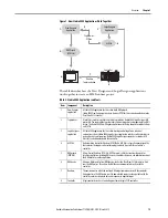
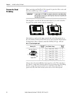
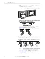
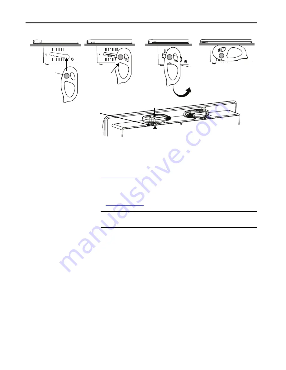
Initially, you secure the terminal in the panel by sliding each lever to a position
that is one or two notches greater than the final lock position. For example, if the
final lock position is 3, slide each lever to position 4 or 5.
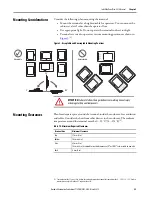
Follow the locking sequence and lever orientations for each terminal as shown in
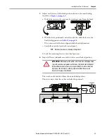
You then adjust each lever to its final lock position in the same sequence as shown
in
.
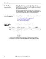
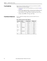
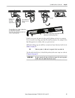
1
Flat Side
Knob on reverse
side of lever
inserts into
large end of slot
1
2
3
4
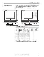
The edge of the bezel has alignment indentations
to assist with the lever position.
The notch on the outside of the lever shows that
the lever is locked in position 3.
You can use an erasable marker or grease pencil to mark the
indentations for visibility of slot positions.
Inner notch on lever
shows current lever
position.
TIP
If the lock position is 6, slide lever to large end of slot or insertion hole.
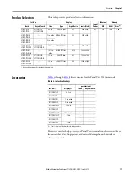
IMPORTANT
This process equalizes the pressure of the levers against the panel at a gradual
rate that reduces the probability of broken clamps.
Содержание Allen-Bradley PanelView 5510 Series
Страница 6: ...6 Rockwell Automation Publication 2715P UM001C EN P March 2019 Table of Contents Notes...
Страница 10: ...10 Rockwell Automation Publication 2715P UM001C EN P March 2019 Preface Notes...
Страница 86: ...86 Rockwell Automation Publication 2715P UM001C EN P March 2019 Chapter 5 Install and Replace Components Notes...
Страница 92: ...92 Rockwell Automation Publication 2715P UM001C EN P March 2019 Chapter 6 Update Firmware Notes...
Страница 108: ...108 Rockwell Automation Publication 2715P UM001C EN P March 2019 Index Notes...
Страница 109: ...Rockwell Automation Publication 2715P UM001C EN P March 2019 109 Index Notes...
Страница 110: ...110 Rockwell Automation Publication 2715P UM001C EN P March 2019 Index Notes...
Страница 111: ......


