background image

RHOTHETA User Manual RT-800


Page 103 of 192 

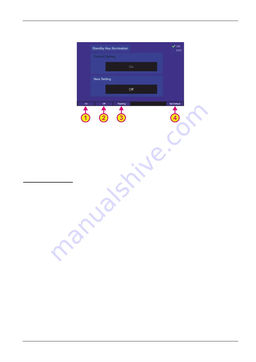
Following dialog opens (s. Fig. 95). 


Fig. 95 Changing the standby key illumination setting 

o

  Choose the “On”, “Off” or “Flashing” hotkey to set the desired variant of the key 

illumination (s. Fig. 95, positions 1, 2 or 3). 

o

  Use the “Set Default” hotkey (s. Fig. 95, position 4) to reset the value to the default 

setting (Off). 

o

  Confirm the changed value with “OK” or press “ESC” to leave the dialog without 

changing the previous setting. 


STNBY Deactivation 

This setting defines, which event can return the RT-800 device from the standby mode to the 

normal operation. 

  If “Automatic” is set, the device will get back to the normal operation by the occurrence 

of an event, e.g. reception of a valid signal (s. 6.5.1). 

  If “User” is set, the standby mode can only be deactivated manually by pressing any 

key (except the On/Off (“Power”) button). 


Note 

To completely turn off the DCU’s illumination in the “Dark Mode”, the settings “Display 

Brightness” and “Key Illumination” must be set to “Off”. This means that the DCU 

remains dark even if a signal is received.  

The communication with the DCU in this mode can be maintained over NMEA or LAN 

interfaces (using NMEA data protocol), if desired.  


Note 

If the “Dark Mode” is activated while either the main bearing frequency is an 

emergency frequency or a scan with any emergency frequency is active, the 

occurrence of the corresponding signal will be indicated by the acoustic alarm even in 

the “Dark Mode”.  
 
To switch off the alarm in this case, the device must first be returned to the normal 

operation, or a corresponding NMEA sentence (“ALARMCFM”, for more information s. 

“NMEA Protocol Description RT-800”) can be sent out over the NMEA interface to 

confirm the alarm. 
 

Содержание RT-800

Страница 1: ...User Manual RT 800...

Страница 2: ...879 15 Internet www rhotheta de E Mail email rhotheta de Copyright RHOTHETA Elektronik GmbH All rights reserved Issue 2022 07 12 Rev 3 01 b Document ID 12 9 1 0003 3 1 61 Valid for RT 800 systems with...

Страница 3: ...6 1 1 Bearing Indication 21 6 1 2 Bearing Operation 26 6 1 3 Function Channel 16 41 6 1 4 Function Repeat 41 6 1 5 Function Clear 42 6 1 6 Function Autoset Squelch 42 6 2 Scan Page 44 6 2 1 COSPAS SA...

Страница 4: ...8 7 Antenna Alignment 167 8 8 Antenna Connection 168 8 9 DCU Configuration 168 8 9 1 Interface Configuration 168 8 9 2 Audio Line Output Configuration 168 8 9 3 Antenna Unit Configuration 169 8 10 Co...

Страница 5: ...Cleaning 184 12 1 Maintenance 184 12 2 Cleaning 184 13 Appendix 185 13 1 Error Messages 185 13 2 Warnings 185 13 3 Setup Tree View Settings 186 13 4 Default User System Configuration Table 187 13 5 Sc...

Страница 6: ...4 Monitoring mode Indication of frequencies 49 Fig 25 Monitoring mode Example views of the Bearing page 49 Fig 26 Monitoring CP SS mode Example views of the Bearing page 50 Fig 27 Example Timing norma...

Страница 7: ...ing the value for the audio beeper 88 Fig 74 Edit value of the audio line output level 88 Fig 75 Edit value for the speaker 89 Fig 76 Frequency information dialog 89 Fig 77 Locked frequencies Operator...

Страница 8: ...netic variation value 121 Fig 123 Monitoring handling settings 121 Fig 124 Own GPS position dialog 122 Fig 125 Own position in DD format 123 Fig 126 Editing the own GPS coordinates 123 Fig 127 PS Ram...

Страница 9: ...166 Adjust External Speaker Volume dialog 154 Fig 167 Squelch dialog 155 Fig 168 Adjust Brightness dialog 156 Fig 169 Adjust Brightness dialog in night color scheme 156 Fig 170 Example of optimal ante...

Страница 10: ...ven For any questions regarding these safety instructions RHOTHETA Elektronik GmbH can be contacted at any time The observance of the safety instructions will help to prevent personal injury or damage...

Страница 11: ...t the connections with information technology equipment e g industrial computers comply with the IEC 62368 1 EN 62368 1 standards that applies in each case This product may only be opened by authorize...

Страница 12: ...harmful interference to radio or television reception which can be determined by turning the equipment off and on the user is encouraged to try to correct the interference by one or more of the follo...

Страница 13: ...lance and the auto alert function The DF system consists of two units the bearing AU Antenna Unit and the operating device DCU Display Control Unit The bearing antenna is a dipole antenna its housing...

Страница 14: ...View DCU Front Control Elements Pos Element Function Description Control Panel Display of bearing data local control of the direction finder Speaker Audio speaker for received signal volume is adjust...

Страница 15: ...brightness of the display s backlight is driven down to a defined value configurable in the Setup page s 6 4 2 8 but the system continues monitoring the corresponding emergency frequency The display...

Страница 16: ...ing of the squelch level s 6 5 3 Key without specific function 5 TFT full color display Shows the corresponding data content of the current page or dialog Hotkeys for activating variable functions The...

Страница 17: ...7 of 192 Numeric keys for direct numeric input Navigation keys for switching between the pages Within the Setup page the navigation keys have different functions due to the large number of possible se...

Страница 18: ...te control via MOXA allows changing of IP data remotely and offers the possibility of setup the SNMP monitoring for RT 800 if needed Note It is possible to use the MOXA or LAN DCU s for remote control...

Страница 19: ...communication port is internally connected to MOXA for remote control purposes Note Please do not use this port for other purposes or disconnect MOXA if MOXA is used for remote control Power I O Sour...

Страница 20: ...ferent pages are listed on the top line of the screen and the active page is highlighted in light blue Switching between pages is done via the corresponding navigation keys which are located directly...

Страница 21: ...line Navigation line of the screen which allows switching between pages Bearing Scan Decode and Setup Frequency indication Section for frequency channel indication during bearing and scanning The act...

Страница 22: ...ws the time elapsed since the last valid bearing interruption Clear hotkey Resets the internal value of the bearing averaging memory Mutes the acoustic alarm if such occurred s 6 1 2 1 Autoset SQL Squ...

Страница 23: ...symbol indicates a USB connection If a USB stick is connected to the DCU the USB symbol turns green If there is no USB connection available the symbol does not appear If this symbol is green then the...

Страница 24: ...s green and shows an A instead of the numerical value Digital signal level indication Signal level of active bearing frequency channel in or dBm adjustable in the Setup page Digital bearing display In...

Страница 25: ...ce directions TRUE or MAGNETIC s under Setup Display settings Heading pointer Heading direction indicator If Compass is used as Bearing Scale Orientation s under Setup Display settings the heading poi...

Страница 26: ...al level in a graphical way s positions 14 and 16 in Fig 5 The squelch level will then be pictured on the scale of the signal level indication at the manually or automatically adjusted value s positio...

Страница 27: ...value 302 Digital indication of bearing value 300 Reference of the bearing True The digital bearing indication is a 3 digit number rounded to the nearest degree The reference of bearing is summarized...

Страница 28: ...er an emergency signal occurs or an error is detected or operating parameters exceed their specified limits the system will inform the operator by activating an alarm error or warning indication While...

Страница 29: ...e system s basic functions are not affected yet but it is recommended to check the system in order to prevent damages Table 7 Alarms Errors Warnings 6 1 2 2 Frequency Channel Input Dialog The frequenc...

Страница 30: ...roup These buttons are used to navigate from one digit to another inside the input field for new frequency channel If the input of the frequency channel is complete and valid pressing this button save...

Страница 31: ...g the Ship frequency for a duplex channel Coast This hotkey appears only for duplex channels s Fig 10 in the dialog for channel input It allows selecting the Coast frequency for a duplex channel CP SS...

Страница 32: ...he frequency channel using a sophisticated input scheme Depending on the other digit values that are already set the system allows the selection of only correct numbers for the current digit Note If t...

Страница 33: ...on 3 and field C sets the standby frequency to the active bearing frequency and the previously active frequency is set to standby s Fig 9 Fig 9 Swap frequencies If you press Swap hotkey again the freq...

Страница 34: ...Corresponding Cospas Sarsat channels for the entered Cospas Sarsat frequency are shown in the right lower corner of the Standby frequency field They are also shown for the active frequency Note The sq...

Страница 35: ...nel For the non duplex channels the new channel is entered as a number without any additional input Switching from Channel input dialog variant to Frequency input dialog variant while entering a chann...

Страница 36: ...ching from Frequency to Channel input dialog variant when the Active frequency does not belong to marine band will show the Active frequency in MHz and the Standby input field for the channel input s...

Страница 37: ...re shown in the right lower corner of the Standby frequency field It is also shown for the active frequency 6 1 2 6 Memory Dialog The memory dialog s Fig 5 position 5 provides a list of stored frequen...

Страница 38: ...annel Scan list Fig 15 Memory Dialog Top level List of Elements Pos Element Function New Freq Creates a new entry at the end of the list By pressing this hotkey the Frequency input dialog opens immedi...

Страница 39: ...navigate on the displayed keyboard The right and left arrows are used to navigate on the displayed keyboard while editing the name of a frequency Button OK o On the top level of the memory dialog pre...

Страница 40: ...idual character for the text input The characters are selected by navigating on the virtual keypad using the arrow keys s position 3 Fig 16 The dialog is closed by confirming with the button End of Us...

Страница 41: ...hotkey name indication adopts the value of the previously active frequency so that it can be quickly switched back if needed Note Please verify correct squelch adjustment For squelch adjustment see 6...

Страница 42: ...heading at the time of the bearing mobile installation A change of heading in the meantime must be considered 6 1 5 Function Clear The function Clr s Fig 5 position 8 clears the internal bearing value...

Страница 43: ...hich allows switching between these squelch adjustment possibilities For further information please refer to chapter 6 5 3 If any scan algorithm is activated this hotkey is designated with Squelch or...

Страница 44: ...Bearing page Fig 18 shows the most important elements of the Scan page Fig 18 Scan page General view Indication on Scan Page Pos Element Meaning Description Start Scan Activates the currently marked...

Страница 45: ...e Pressing this button on the Bearing page while any scan procedure is currently active will open a confirmation dialog for ceasing the currently running scan procedure s Fig 23 Confirming with OK ter...

Страница 46: ...ows the direct opening of a frequency for bearing which was found in an earlier scan cycle Fig 19 Cospas Sarsat scan mode with the last result indication During any scan is active the field for the da...

Страница 47: ...ct the corresponding line on the Scan page and press OK or the hotkey Start Scan s Fig 22 position 1 Fig 22 Cospas Sarsat Scan mode has been activated o Pressing the hotkey Stop Scan s Fig 22 position...

Страница 48: ...e used as the main bearing frequency Monitoring scan has two different modes of operation which depends on the main bearing frequency o Monitoring normal the mode of operation with any main frequency...

Страница 49: ...e next monitoring frequency Active reception will be interrupted after 30 seconds for a short moment in order to examine the other monitoring frequencies safety function This behavior can be changed u...

Страница 50: ...ng mode with a non CP SS frequency as the main bearing frequency s 6 2 2 2 The CP SS monitoring procedure will first look for the COSPAS SARSAT signal and then if no pulse has been detected for 60 sec...

Страница 51: ...s ID Only Signals transmitted by emergency transmitters PLB ELT are modulated with a typical sweeping tone In order to exclude false alarms caused by disturbing signals or by not authorized radio comm...

Страница 52: ...30 this mode will be terminated Fig 30 Confirming of leaving the scan mode o Pressing the hotkey Go to Result s Fig 29 position 3 during the monitoring is currently running will terminate the scan mo...

Страница 53: ...Fig 32 position 1 or 2 to switch to the Channel or Cospas Sarsat input mask Fig 32 Editing the current frequency o Pressing the hotkey Time def s Fig 31 position 2 will set the hold time duration of s...

Страница 54: ...PLB The alarm is only triggered if an ELT PLB signature is set and the corresponding modulation has been detected Otherwise the alarm will not be activated 2 Alarm is never triggered regardless of wh...

Страница 55: ...nels are selected one cycle of the scan procedure takes approximately one second In fast channel scan mode the auto squelch is set automatically The behavior of the auto squelch can be slightly influe...

Страница 56: ...ve the squelch level scanning stops as well at these interferences they are interpreted as signals This may be avoided by adjusting the squelch level manually adjusting the SNR value Because of this i...

Страница 57: ...e with activated scan After you have confirmed the special dialog s Fig 36 this mode will be terminated Fig 36 Confirming of leaving the scan mode o Pressing the button OK during the time of the activ...

Страница 58: ...nput field or use one of the hotkeys s Fig 38 positions 1 and 2 to open the Channel or Cospas Sarsat input mask Fig 38 Input of a new frequency to be scanned o The hotkey Edit Freq s Fig 37 position 2...

Страница 59: ...efined from 156 050 MHz Channel 01 to 157 425 MHz Channel 88 and is scanned with 5 kHz frequency steps without gaps The frequency range cannot be changed The duration of one scanning cycle is approx 3...

Страница 60: ...cy band which are above the squelch level scanning stops as well at these interferences they are interpreted as signals This may be avoided by adjusting the squelch level manually using the Up and Dow...

Страница 61: ...rked s Fig 41 position 4 By pressing this hotkey the dialog for editing the Exclude List will be opened s 6 2 4 3 o Pressing the hotkey Go to Result s Fig 41 position 5 during the marine scan is curre...

Страница 62: ...an algorithm will stay on the actively received frequency as long as the user terminates the scan or skips the current frequency 6 2 4 3 Exclude List for Marine Scan and Scan List modes The Exclude Li...

Страница 63: ...n is finding COSPAS SARSAT beacons which usually transmit a signal on one of the 406 MHz frequencies and additionally a continuous signal on other emergency frequency mostly 121 500 MHz A COSPAS SARSA...

Страница 64: ...are freely selectable Designation of the currently active scan mode Main bearing frequency currently active Scan frequencies here only one of the freely selectable frequencies is set Fig 44 SAR scan I...

Страница 65: ...g the OK button will be adopted as the main frequency and the system will change to a normal bearing mode 6 2 5 1 Timing of the SAR Scan Operation The SAR scan procedure has slightly different timing...

Страница 66: ...COSPAS SARSAT pulse which enables the efficient scanning of the selected frequencies without missing the next COSPAS SARSAT pulses Fig 47 Example Timing SAR scan if only COSPAS SARSAT frequency is det...

Страница 67: ...will be terminated Fig 50 Confirming of leaving the scan mode o Pressing the hotkey Go to Result s Fig 49 position 3 during the scan mode is currently running will terminate the scan mode adopt the fr...

Страница 68: ...the COSPAS SARSAT frequency is marked s Fig 52 position B By pressing this hotkey a COSPAS SARSAT scan will be started in order to find an active COSPAS SARSAT frequency during SAR scan algorithm o Pr...

Страница 69: ...one scan procedure The scan algorithm in the full scan list mode compares Search List accessible over Edit Scan and Exclude List s 6 2 4 3 and out of this comparison it generates an internal list of f...

Страница 70: ...ton HOME while on Bearing page Then the direction finder changes to the bearing of the frequency which was set before the scan mode was started o The hotkey Excl On Off is only visible if Marine scan...

Страница 71: ...be skipped anymore when the results are scanned after pressing Scan Results Pressing Scan Results s Fig 55 position 3 starts the scan list mode which runs only around the frequencies which had a resul...

Страница 72: ...ncy Input Dialog s 6 1 2 2 which allows modifying the Stop Frequency of the currently marked frequency range Note Start and stop frequencies must be in the same frequency band s Table 1 in chapter 4 a...

Страница 73: ...key Edit Time s Fig 57 position 2 will open a dialog for editing the time of staying on the actively received frequency before continuing with the scan procedure Pressing the hotkey Signal Sql hotkey...

Страница 74: ...Decode page the active COSPAS SARSAT frequency is determined by the following conditions By switching from Bearing page the COSPAS SARSAT frequency which was active in the Bearing page will be adopte...

Страница 75: ...ing this button always leads to the Bearing page Even an opened dialog will be closed If a sub dialog is opened pressing this button will close it and lead to the Bearing page without saving the chang...

Страница 76: ...lse is received the hotkey 406 025 changes its label to Confirm and blinks in yellow s Fig 59 Additionally an acoustic warning tone is emitted Press Confirm in order to accept the message and to clear...

Страница 77: ...equency is also displayed in the label of the hotkey for adjusting frequency Note GPS TB data can be shown only if compass and GPS are available The distance can be shown without connection of vessels...

Страница 78: ...s Fig 61 position 3 will change to the COSPAS SARSAT Bearing and List view s 6 3 4 o Like in the COSPAS SARSAT List view it is possible to delete all stored COSPAS SARSAT messages by pressing the hotk...

Страница 79: ...ayed COSPAS SARSAT message to the Bearing page s Fig 63 position 4 See also chapter 6 3 5 Export to Bearing Page o Like in the COSPAS SARSAT List view it is possible to delete all stored COSPAS SARSAT...

Страница 80: ...aring on the Bearing page In order to remove the indication of the GPS Arrow from the Bearing page keep the Clr hotkey pressed for a few seconds until the arrow disappears the indication of GPS true b...

Страница 81: ...an ELT signal will be detected and the alarm will be provided Note Incorrect settings may lead to considerable malfunctions of the DF system RT 800 Therefore sensitive parameters concerning the beari...

Страница 82: ...d password has to be entered first whereupon the new password can be defined System Info Opens a dialog which shows the information about the revisions status of the used system components s 6 4 1 9 F...

Страница 83: ...the general settings dialogs is accomplished Inside the general settings dialogs the DEL button is used to clear the whole input at once On the top level of the Setup page this button has no function...

Страница 84: ...s level to Administrator e g after the hotkey Set Operator was pressed using the default password admin All essential settings of the system that have a direct influence on the bearing must be done by...

Страница 85: ...DCU has an internal speaker that can be used to monitor the audible signals or acoustic alarms Alternatively the external speaker can be used e g for release an alarm on the ship 6 4 1 5 Set Operator...

Страница 86: ...he next instructions in order to change the password Input field for the password Virtual keypad Fig 70 Changing the administrator password Input delete key End of input First the old password will be...

Страница 87: ...ng the operator access level Fig 71 Edit value dialog for access level 1 Pressing the hotkey Set Admin will lead to the Set Admin dialog where the password input is required s 6 4 1 5 Pressing the hot...

Страница 88: ...the changes press ESC at any step and escape the dialog without saving the new value Edit value for setting Audio Line Output Fig 74 Edit value of the audio line output level 1 In the edit value dialo...

Страница 89: ...ation Fig 76 Frequency information dialog Explanation of the abbreviations Hotkey for additional information about locked frequencies o The frequency bands that are marked with Std are basic frequency...

Страница 90: ...fo dialog The window which is shown in Fig 78 appears 2 To lock a single frequency press the hotkey Add Freq The Frequency input dialog appears for further information s 6 1 2 2 where a frequency chan...

Страница 91: ...quencies the dialog will be left by pressing ESC the dialog will be closed without saving any changes That means the list will not be deleted and is accessible again after pressing the hotkey See lock...

Страница 92: ...Display page enables modifying of settings that affect the graphical representation of the application After pressing the Display navigation key following menu page opens s Fig 80 Fig 80 Setup page Di...

Страница 93: ...n there is no dialog opened pressing this button will go back to the last activated page The Bearing page is the endpoint Pressing this button always leads to the Bearing Page Even an opened dialog wi...

Страница 94: ...etting using the numeric keys of the keypad o Use the hotkey Endless to set the bearing hold time to an endless value which means that after the signal was interrupted the last valid bearing informati...

Страница 95: ...North 0 alignment of the antenna for permanent installation Note If the Rel Bearing reference direction is chosen and the compass data is available then the heading value in the triangle on the top o...

Страница 96: ...tic North Up are possible to select If Compass is used as Bearing Scale Orientation the heading pointer shows a value in that corresponds to the current alignment in space and the compass rose rotates...

Страница 97: ...configure the indication of frequency channel which is then shown on the Bearing page in the left upper corner of the display s Fig 85 Fig 85 Types of the frequency channel indication To change the ty...

Страница 98: ...setting is marked by the green frame Choosing the kilometers as the distance indication unit Choosing the nautical miles as the distance indication unit Choosing the default setting for the distance...

Страница 99: ...ht Sensor Settings The light sensor is used in the DCU to adjust the brightness of the display legends and Keys s 6 5 4 automatically according to the ambient light level In this menu point which cont...

Страница 100: ...he New Setting input field using the numeric buttons of the DCU keypad o Use the Set Default hotkey to reset the value to the default setting o Confirm the changed value with OK or press ESC to leave...

Страница 101: ...time delay value for the light sensor o Type the new value for the delay value of the light sensor in the New Setting input field using the numeric buttons of the DCU keypad o Use the Set Default hotk...

Страница 102: ...in the New Setting input field using the numeric buttons of the DCU keypad or use the hotkey Off s Fig 94 position 1 in order to set the standby brightness to a black screen value If the setting Off i...

Страница 103: ...andby mode can only be deactivated manually by pressing any key except the On Off Power button Note To completely turn off the DCU s illumination in the Dark Mode the settings Display Brightness and K...

Страница 104: ...activation is marked Following dialog opens s Fig 96 Fig 96 Changing the standby deactivation setting o Press the hotkey Automatic s Fig 96 position 1 in order to enable the automatic standby mode dea...

Страница 105: ...nation is completely turned off for the Dark Mode Display Brightness and Key Illumination are set to Off and STNBY Deactivation is set to User leaving the Standby Mode Settings dialog by pressing OK w...

Страница 106: ...2 10 Night Mode Settings The night mode settings allow the adjustment of the night mode behavior To change these settings press the hotkey Edit Value while the line Night Mode Settings is marked s Fi...

Страница 107: ...mode is activated after 30 seconds when a certain threshold for ambient brightness measured by the light sensor is reached This threshold can be defined with the Activation Threshold setting s below T...

Страница 108: ...default value Off o Confirm the changed value with OK or press ESC to leave the dialog without saving the change Activation Threshold This setting can be used to define the ambient brightness level me...

Страница 109: ...new value for the night mode activation threshold in the New Setting input field using the numeric buttons of the DCU keypad o Use the Set Default hotkey s Fig 105 position 2 to reset the value to the...

Страница 110: ...umber of the internal system settings which are only available over the administrator access level All settings are organized alphabetically in order to improve the handling of the page Caution Incorr...

Страница 111: ...point Pressing this button always leads to the Bearing page Even an opened dialog will be closed without adopting the changed values Up and Down arrows are used to move between the system settings Rig...

Страница 112: ...7 Fig 107 Alarm pulse settings Active direction setting defines which direction low or high will lead to an alarm indication This setting is changeable using the hotkeys High active Low active or Edit...

Страница 113: ...09 Setting the alarm mode to Pulse Setting the alarm mode to Continuous Fig 109 Alarm mode dialog Selecting the default value o Pressing the CONT hotkey sets the alarm mode of the alarm pulse to Conti...

Страница 114: ...the hotkey Edit Value s Fig 107 position 5 The related dialog will open s Fig 111 Fig 111 Time on Dialog o Use the number keys of the DCU keypad to enter the new value for the Time On setting o Press...

Страница 115: ...og without adopting the new value by pressing ESC 6 4 3 3 Antenna Mechanical Correction The antenna is to be mounted facing North or 0 direction There is a North respectively 0 marker on the antenna u...

Страница 116: ...stallation is marked by the green frame the following dialog is opened Fig 114 Antenna installation dialog o Pressing the hotkeys Fixed Installation or Mobile Installation sets the corresponding value...

Страница 117: ...ing ESC 6 4 3 6 Beep Tone Decoding Parameters of the menu Beep Tone Decoding control the behavior of the function Fast Channel Scan for the case that an alarm should be triggered only if an audio sign...

Страница 118: ...ways to change this setting either using the Freq Low or the Edit Value hotkey s Fig 116 positions 2 and 4 both of these hotkeys will open the same dialog Fig 118 Dialog for the lower frequency Beep...

Страница 119: ...es the duration until the dialog for frequency input s 6 1 2 2 closes automatically if no interaction of the user happens o By pressing the OK button or hotkey Edit Value while the setting Frequency I...

Страница 120: ...ntered for the first time when no frequency is locked yet Fig 121 Locked frequencies list Administrator view o The use of this dialog is described in chapter 6 4 1 8 please refer to it for more inform...

Страница 121: ...o Press the hotkey Set Default s Fig 122 position 3 to use the default value Disabled o Confirm the setting with OK or leave the dialog without adopting the new value by pressing ESC 6 4 3 10 Monitor...

Страница 122: ...tem it is possible to enter the GPS coordinates of the location own position Entry in two formats is possible DMS and DD This setting has no default value respectively it is set to Disabled Note If va...

Страница 123: ...otkeys while editing the coordinates s N S Lattitude and W E Longitude in Fig 126 Fig 126 Editing the own GPS coordinates o Press the hotkey Save s Fig 126 to save the entered values o Confirm the set...

Страница 124: ...s Fig 127 which will then appear in the New Setting field Comp On The AU will use compass values to compensate the contouring error Comp Off The AU will not use compass values to compensate the contou...

Страница 125: ...utton or hotkey Edit Value s Fig 106 while the setting Scan Page Settings is marked the following dialog is opened s Fig 129 Setting the Go to Bearing Page behavior Setting the Stay on Scan Page behav...

Страница 126: ...marked s Fig 130 position 1 Fig 130 Selecting the time settings The following dialog appears s Fig 131 Fig 131 Time settings dialog Note If you press OK in this view the current settings will be inter...

Страница 127: ...ble o By default the current seconds value is inherited to the new setting To reset the seconds value to 00 press the Reset seconds hotkey s Fig 132 position 2 o Use the Set Default hotkey s Fig 132 p...

Страница 128: ...the Reset Values hotkey to reset the value to the default value UTC 00 00 o Confirm the changed value with OK or press ESC to leave the dialog without changing the current setting Display Time With th...

Страница 129: ...lue to the default value Local o Confirm the changed value with OK or press ESC to leave the dialog without changing the current setting Summer Time With this setting it is possible to select whether...

Страница 130: ...ummer time setting o Choose the On or Off hotkey to set the desired variant of the time indication s Fig 138 positions 1 or 2 o Use the Set Default hotkey s Fig 138 position 3 to reset the value to th...

Страница 131: ...139 Setup page Interface settings Indication on Setup Page Interface Settings Pos Element Meaning Description COM Monitor Using this hotkey opens the dialog for monitoring the data that is currently b...

Страница 132: ...the whole input at once On the top level of this page this button has no function Numeric keys are used to enter the numerical characters inside the dialogs On the top level of the page they have no f...

Страница 133: ...re not used they will appear as hotkeys in the dialogs as possible ports to use for the NMEA remote communication Nevertheless the communicatoin port COM3 is internally connected to MOXA for remote co...

Страница 134: ...remote control PC Caution If communication ports other than the default port COM3 are not used they will appear as hotkeys in the dialogs as possible ports to use for the NMEA remote communication Nev...

Страница 135: ...A remote communication Nevertheless the communicatoin port COM3 is internally connected to MOXA for remote control purposes Please do not adjust other COM ports for remote control use COM3 for purpose...

Страница 136: ...The DF only reacts to the NMEA request sentences if the address ID in the sentence is equal to the address which is selected via this setting or has the value 255 if the ID was not set For further exp...

Страница 137: ...dit Value while the setting LAN Configuration is marked s Fig 139 Following sub menu will appear s Fig 145 Fig 145 LAN configuration menu Following settings can be configured Mode of the IP address as...

Страница 138: ...and Dynamic IP positions 1 and 2 s Fig 145 so that the value of this setting is changed without opening the dialog or it can be set over the corresponding dialog after pressing the hotkey Edit Value s...

Страница 139: ...e netmask press the hotkey Edit Value while this menu point is marked s Fig 145 position 3 Following dialog opens s Fig 148 Fig 148 Changing the netmask value o Use the number keys of the DCU keypad t...

Страница 140: ...etting in the LAN Configuration dialog always confirm the changed settings with OK on the top level second time o After confirming the changed settings on the top level of the dialog a dialog for rest...

Страница 141: ...rm the changed settings with OK on the top level second time o After confirming the changed settings on the top level of the dialog a dialog for restart the system is opened s Fig 150 6 4 4 4 NMEA Com...

Страница 142: ...or 3 on the top level dialog NMEA Compass Configuration s Fig 152 the value of the Port setting can be changed without opening the corresponding dialog o Pressing the hotkey Edit Value the following s...

Страница 143: ...ng sub dialog will be opened s Fig 154 Fig 154 Compass baud rate setting o Choose the new baud rate value in the drop down menu o Press the hotkey Reset Values to use the default value of 4800 o Confi...

Страница 144: ...ting field 1 Selecting the xxHDG heading deviation and variation header position 1 2 Selecting the xxHDT true heading header position 2 3 Selecting the xxHDM magnetic heading header position 3 o Press...

Страница 145: ...button OK or hotkey Edit Value while the setting NMEA GPS is marked s Fig 139 Following sub menu will appear s Fig 156 Fig 156 NMEA GPS configuration settings The NMEA GPS configuration is accomplishe...

Страница 146: ...hoose the new setting using one of the hotkeys which will then appear in the New Setting field o Press the hotkey Set Default s Fig 157 position 4 to use the default value No GPS o Confirm the setting...

Страница 147: ...able OUT lines where different signals can be provided o In order to define which signals are to be allocated to the IOs select the setting GPIOs Power S Connector s Fig 139 and press OK or the hotkey...

Страница 148: ...our setting possibilities for this pin 1 Alarm Out Choosing this setting connects the programmable output pin with the pin for the alarm relay s Fig 161 position 2 2 Squelch Out Choosing this setting...

Страница 149: ...o Choose the new setting using one of the hotkeys s Fig 161 which will then appear in the New Setting field o Press the hotkey Set Default s Fig 161 position 5 to use the default value Alarm Out o Con...

Страница 150: ...ndication on Setup Page Service Menu Pos Element Meaning Description Top line Navigation line of the screen which allows switching between setup menus General Display System Interface and Service Upda...

Страница 151: ...by RHOTHETA you can input it using this dialog The Input License dialog is opened by pressing the corresponding hotkey when the service menu is opened s Fig 162 position 3 o You can input the new lice...

Страница 152: ...User Manual RT 800 Page 152 of 192 Fig 164 Input of a new license o After confirming the new valid license with OK a dialog opens which requests the restart of the system s Fig 165 Fig 165 New license...

Страница 153: ...ode the function of the button pressed is not performed at the first press o The display is turned on again by default when an event occurs e g signal level rises above squelch level alarm occurs scan...

Страница 154: ...ent of the squelch is crucial for attaining the optimal sensitivity of the signal reception The more sensitively the system works the greater signal range operating distance can be achieved Especially...

Страница 155: ...the Off hotkey s field B To apply the function of the automatic squelch adjusting to all the stored frequencies press the hotkey Autoset All s field C Note While operating on the noise edge or inside...

Страница 156: ...de available which facilitates a quick change to the darker color scheme of the display at the push of a button or automatically depending on the chosen settings for night mode settings please see the...

Страница 157: ...ease pay attention that this will not simply change the current brightness If you change the brightness settings in the Auto mode the new values will be coupled to the light sensor s middle position a...

Страница 158: ...nal this pin is connected to ground active by the means of an open collector output Max current 200 mA 4 Alarm Relay Optional alarm contact mechanical relay as NOC Normal Opening Contact Max 1 A at 30...

Страница 159: ...Connecting Cable DCU AU 7 2 1 Pinning Antenna Unit Connector S Fig 3 position 5 Contact Pin Signal 3 12 to 30 V DC Power connection of Antenna Unit Note Power supply includes a shortcut protection 8 5...

Страница 160: ...aces COM1 COM2 and COM3 s Fig 3 positions 6 8 9 have the same pinning These interfaces should be used for connection of COMPASS of the vessel GPS Receiver ECDIS Remote Control Note When connecting to...

Страница 161: ...r purposes or disconnect MOXA if MOXA is used for remote control 7 4 LAN Interface The LAN interface s Fig 3 position 7 can be used for connection of ECDIS or other Remote and Control Devices for conf...

Страница 162: ...switching on the DCU the current IP address of the IP Audio Encoder is output to connected headphones This is only used during configuration process 4 Audio Ethernet Ethernet connection of IP Audio En...

Страница 163: ...g 1 N Neutral IEC 60320 C14 inlet for use of power cords with IEC 60320 C13 plugs 115 230 Volts 1 0 0 5 Ampere 50 60 Hz 2 PE protective earth 3 L Line 4 Built In Fuse replaceable Embedded replaceable...

Страница 164: ...for all bearing systems 8 2 Installation Recommendation The quality of the bearing results depends largely on the position of the antenna A position has to be found where the transmitter s wavefield...

Страница 165: ...el Zone There must be a direct line of sight between the transmitter ship and the antenna unit Furthermore the fresnel zone must be free of any obstacles Fig 171 Line of Sight and Fresnel Zone In case...

Страница 166: ...verview of favorable and unfavorable Installation Locations The drawings below show a summarization of effects to be considered while selecting installation sites The first one focuses on effects in m...

Страница 167: ...reat influence on the direction finding accuracy due to reflected radio waves like any other metallic structure in proximity of the direction finder The RHOTHETA Lightning Protection Rod uses special...

Страница 168: ...Internally the control panel of the RT 800 display with buttons is connected to a serial to ethernet converter by a serial line This implies that the same serial configurations must be used in both t...

Страница 169: ...purposes of use fixed or mobile installation the setting Antenna Installation can be set s 6 4 3 4 8 10Configuration of Remote Control over IP See also 8 13 Example of complete Network Scenario 8 10 1...

Страница 170: ...available in your network the RT 800 will get an initial IP address depending on your DHCP router settings You can use an IP scanner or just look at your router configuration console or as example wi...

Страница 171: ...info Fixed MAC address of the RT 800 MOXA device Used for DHCP router reservation table Basic Infos Name of RT 800 MOXA device Internal serial Settings Attention Any change of this values will result...

Страница 172: ...800 DCU contains an industrial audio streaming device live IP audio encoder BARIX Instreamer for this purpose Fig 177 Audio streaming to LAN connector The BARIX Intreamer device supports a lot of stre...

Страница 173: ...rix device is preconfigured after delivery to DHCP mode If NO DHCP server is available and no static IP mode is configured it can take up to 4 minutes before the IP address will be announced over the...

Страница 174: ...P address Valid Gateway address if routing streaming to other devices outside the local network Audio configuration recommended audio settings Streaming configuration recommended settings Individual p...

Страница 175: ...s the recommended solution and provided by RHOTHETA This device Exstreamer decodes audio streams and play out the received audio signals to amplifiers or speakers Supporting a large number of protocol...

Страница 176: ...The IP address will be announced after Power On over the headphone connector This can take up to 4 minutes if no DHCP server is available at the connected LAN network The IP address fo this Exstreamer...

Страница 177: ...ernet connection with port forwarding is used For professional uses with e g VPN connection no port forwarding is necessary because then all devices are working virtually in the same network without t...

Страница 178: ...4 995 MHz Option F2 UHF Air Band 240 000 246 000 MHz 225 000 399 975 MHz Option F3 COSPAS SARSAT 400 000 406 092 MHz UHF FM Band 406 100 410 000 MHz 406 100 470 000 MHz Option F4 Receive Frequency Tun...

Страница 179: ...justable from 200 mVpp to 2 Vpp Operating Voltage 110 230 VAC 50 60 Hz Power Consumption Nominal 30W 230V Current Consumption Max 1A typical 0 1A 230VAC typical 0 2A 110VAC Interfaces o 3x NMEA 0183 R...

Страница 180: ...RHOTHETA User Manual RT 800 Page 180 of 192 9 2 Mechanical Characteristics 9 2 1 DCU Dimensions built in version Measuring units mm millimeters Fig 179 RT 800 mechanical dimensions built in version...

Страница 181: ...mensions tabletop version Measuring units mm millimeters Fig 180 RT 800 mechanical dimensions tabletop version 9 2 3 DCU Mechanical Characteristics Weight Approx 5900 g Permitted operating temperature...

Страница 182: ...RHOTHETA User Manual RT 800 Page 182 of 192 9 2 4 Antenna Unit Dimensions Measuring units mm millimeters Fig 181 Antenna Unit mechanical dimensions...

Страница 183: ...182 Antenna Unit mast flange mechanical dimensions 9 2 6 Antenna Unit Mechanical Characteristics Weight Approx 5200 g Permitted operating temperature 40 C1 to 60 C Permitted storing temperature 55 C t...

Страница 184: ...sal 11 Disposal outside the European Union For proper disposal of used electronic equipment in accordance with the respective national regulations in countries outside the European Union please check...

Страница 185: ...uit Please connect AU properly and press Clr Antenna Unit Incorrect connection of AU supply short circuit or very low supply voltage 13 2 Warnings Warning message Error location Cause Warning 02 NoCom...

Страница 186: ...RHOTHETA User Manual RT 800 Page 186 of 192 13 3 Setup Tree View Settings...

Страница 187: ...Bearing Scale Offset 0 Bearing Scale Orientation Compass Channel Indication Channel Distance Unit km Level Unit Light Sensor Settings Minimum Range 0 Maximum Range 100 Time Delay 20 sec STNBY Mode Set...

Страница 188: ...Ram Compass Compensation On S N Ratio AutoSQL dB 6 Scan Page Settings OK Stay on Scan Page Time Settings Current UTC Time hh mm ss Timezone UTC 00 00 Display Time Local Summer Time Off SETUP INTERFAC...

Страница 189: ...RHOTHETA User Manual RT 800 Page 189 of 192 13 5 Scan Page Tree View Settings...

Страница 190: ...161 700 MHz 23 157 150 MHz 161 750 MHz 24 157 200 MHz 161 800 MHz 25 157 250 MHz 161 850 MHz 26 157 300 MHz 161 900 MHz 27 157 350 MHz 161 950 MHz 28 157 400 MHz 162 000 MHz 60 156 025 MHz 160 625 MH...

Страница 191: ...narrow 118 0000 118 010 8 33 kHz narrow 118 0083 118 015 8 33 kHz narrow 118 0167 118 020 Not valid 118 025 25 kHz wide 118 0250 118 030 8 33 kHz narrow 118 0250 118 035 8 33 kHz narrow 118 0333 118...

Страница 192: ...finder Deg Degree 60 ELT Emergency Locator Transmitter GND Ground GPS Global Positoning System ID Identification IP Ingress Protection rating IP67 LAN Local Area Network LCD Liquid Crystal Display LED...

Отзывы: