


33
Endura
®
Delta
en
Installer
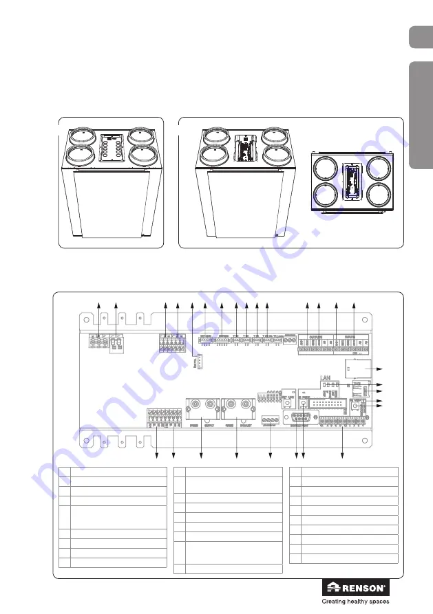
7 • Connection diagram Endura Delta
7.1 • Connection printed circuit board Endura Delta
• Unscrew the cover on
top of the Endura Delta
(6 screws).
• You can now access the connection printed circuit board.
➀
➁
11
12
13
14
18
16
15
1
5
6
7
10
8
9
2
3
4
20
21
24
25
26
27
22
23
17
19
28
1 Power 230V
2 Preheater connection
3 Supply fan power
4 Extraction fan power
5 T11 extract air temperature and
relative hu VOC + CO
2
sensor
6 TouchDisplay front panel connection
7 Bypass connection
8 T12 extract air temperature sensor
9 T22 supply air temperature sensor
10 T21 outdoor air temperature sensor
11 T21bis outdoor air temperature
sensor
12 Output contact 24 V DC
13 Output contact 0-10 V
14 Input contact 24 V DC
15 Input contact 0-10V
16 RJ45 connector (Ethernet link)
17 Control ethernet conn
STATIC/DHCP programmable with a
push-button
18 Micro SD card holder
19 ControlLED SD card
20 Button to lock the SD card
21 10-pole 4-position switch connection
22 IP address button
23 Service port
24 Master TouchDisplay connection
25 Exhaust pressure lines
26 Supply pressure lines
27 Extraction fan control
28 Supply fan control
Содержание Endura Delta 330
Страница 1: ...Endura Delta Installer User manual...
Страница 136: ...136 Endura Delta en...
Страница 137: ...137 Endura Delta en...
Страница 138: ...138 Endura Delta en...
Страница 139: ...139 Endura Delta en...


