Redpine Signals, Inc.
Page 8
R
R
S
S
-
-
W
W
C
C
-
-
3
3
0
0
1
1
E
E
v
v
a
a
l
l
u
u
a
a
t
t
i
i
o
o
n
n
B
B
o
o
a
a
r
r
d
d
U
U
s
s
e
e
r
r
G
G
u
u
i
i
d
d
e
e
V
V
e
e
r
r
s
s
i
i
o
o
n
n
2
2
.
.
5
5
1
1
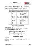
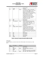
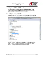
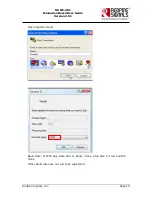
If the EVB needs to be connected to the serial interface of an MCU platform, this
header can be used. The voltage level of the UART Tx and Rx pins of this header
is 3.3V. The Ground pin should be connected to a corresponding ground signal of
the MCU board. For RS-WC-301 the header assignment is shown below
Pin
number Pin name
Direction Description
1
NC
-
This pin must be left
unconnected
2
NC
-
This pin must be left
unconnected
3
NC
-
This pin must be left
unconnected
4
UART-RX
Input
UART Rx pin of the module
5
UART-TX
Output
UART Tx pin of the module
6
UART-CTS
-
Not used in current
firmware. Should be left
unconnected
7
UART-RTS
-
Not used in current
firmware. Should be left
unconnected
8
GND
-
Ground
9
GND
-
Ground
10
GND
-
Ground
Table 1:UART Header (RS-WC-301)
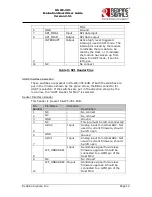
Mode Selection Switches
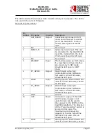
To select the interface in the EVB, configure the individual switches of Mode
Selection Switch bank as shown in the below table.
Switch #
UART Mode SPI Mode
USB
1
ON
ON
ON
2
ON
OFF
ON
3
ON
ON
OFF
4
ON
ON
ON
Table 2: Interface Selection
Card Ready
The Card Ready LED glows after the module has booted up successfully. It is an
indication that the EVB is ready to accept commands from the Host.
WIFI Activity


