Redpine Signals, Inc.
Page 12
R
R
S
S
-
-
W
W
C
C
-
-
3
3
0
0
1
1
E
E
v
v
a
a
l
l
u
u
a
a
t
t
i
i
o
o
n
n
B
B
o
o
a
a
r
r
d
d
U
U
s
s
e
e
r
r
G
G
u
u
i
i
d
d
e
e
V
V
e
e
r
r
s
s
i
i
o
o
n
n
2
2
.
.
5
5
1
1
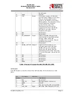
MHz
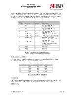
6
GND
-
Ground
7
SPI_MOSI
Input
SPI data input
8
SPI_MISO
Output
SPI data output
9
INTERRUPT
Output
Active high, level triggered
interrupt, used in SPI mode. The
interrupt is raised by the module
to indicate there is data to be
read by the Host, or to indicate
the module has woken up from
sleep. In UART mode, it can be
left open
10
NC
-
No connect
Table 5: SPI Header Pins
UART Interface Selection
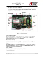
These switches are present in RS-WC-301-EVB. If both the switches are
put in the direction shown by the green arrow, the DB9 connector for
UART is selected. If the switches are put in the direction shown by the
red arrow, the “UART Header for MCU” is selected.
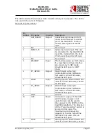
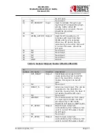
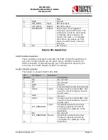
Sensor Interface Header
This header is present RS-WC-301-EVB.
Pin
Number
Pin Name
Direction
Description
1
NC
-
No connect
2
NC
-
No connect
3
GND
-
Ground
4
NC
-
This pin must be left unconnected
5
ADC2
Input
Analog input to internal ADC. Not
used in current firmware, should
be left open
6
GND
-
Ground
7
ADC1
Input
Analog input to internal ADC. Not
used in current firmware, should
be left open
8
WF_HNDSHKE1
Input
Handshake signal for wireless
firmware upgrade. Should be
connected to a GPIO pin of the
Host MCU
9
NC
-
No connect
10
WF_HNDSHKE2 Ouput
Handshake signal for wireless
firmware upgrade. Should be
connected to a GPIO pin of the
Host MCU


