UM-1096
Revision A
10
3.6
Sensor Installation and Replacement
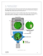
The SensePoint utilizes RC Systems’ Gen II Smart Sensors. These sensors come factory installed and
provide our highest level of performance with increased accuracy and signal to noise ratio. The 8-
conductor Smart Sensor interface connector attaches to the J1 connector on the base board, and the
detector detects the type of sensor automatically. This makes it easier than ever to switch from any of
our electrochemical Smart Sensors to any of our bridge (infrared, catalytic bead and PID) Smart Sensors
without having to reconfigure wiring.
3.7
Smart Sensors
WARNING
: Prior to performing sensor replacement ensure the area has been declassified.
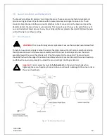
To install a new sensor, simply remove the sensor head cap, remove the old sensor assembly and align
the alignment arrows on the new sensor assembly with the sensor head body and press the sensor
assembly toward the sensor head body until it has fully seated in the connector. The sensor board
should be flush with the edge of the sensor head body when fully seated. Reinstall the sensor head cap
and follow the on-screen prompts to upload the sensor settings into the gas detector.
Important
: Sensor assembly must be
fully inserted
into the sensor head body when
tightening the sensor head cap. Failure to do so could result in damage to the sensor and/or
the sensor head body.
Figure 7 Stainless Steel Sensor Head
!
Содержание 10-0517
Страница 4: ...UM 1096 Revision A III Drawings 44...
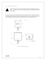
Страница 10: ...UM 1096 Revision A 5 Figure 2 Remote Sensor Enclosure Mounting Dimensions...
Страница 26: ......
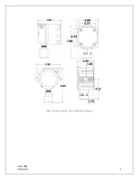
Страница 49: ...UM 1096 Revision A 44 Appendix 9 Drawings Drawings Figure 13 Mounting Dimensions...
Страница 50: ...UM 1096 Revision A 45 Figure 14 10 0517 CPU Board Figure 15 10 0533 I O Board...
Страница 51: ...UM 1096 Revision A 46 Figure 16 10 0532 Modbus Relay Board...


