UM-1096
Revision A
36
Dat a Fr om
Sour ce Sensor
Remot e Sensor No
Mi n Raw 800
Max Raw 4000
Remot e I D 1
Al i as 31001
Dat a Fr om
I nt er f ace COM1
Fi l t er ( second) 5
Byt e Or der ABCD
Pol ar i t y Negat i ve
Heat er Enabl ed No
Heat ( degC) 25
Dat a Fr om
Set Vol t age >
Set Bal ance >
Set PGA >
Mar ker >
Conf i gur e
Tag Measur ement Name
E. Uni t s E. Uni t s
Zer o 0
Span 100
Deci mal Poi nt s 0
Conf i gur e
War mup( m) 1
Cal i br at i on
Zer oSet poi nt 0
SpanSet poi nt 50
Temp Comp
- 40C g1. 000: o+0. 000
- 30C g1. 000: o+0. 000
- 20C
g1. 000: o+0. 000
- 10C
g1. 000: o+0. 000
0C
g1. 000: o+0. 000
10C
g1. 000: o+0. 000
Temp Comp
20C
g1. 000: o+0. 000
30C
g1. 000: o+0. 000
40C
g1. 000: o+0. 000
50C
g1. 000: o+0. 000
60C
g1. 000: o+0. 000
Cal Gai n 1
Gai n Of f set 0
Set Uni t y >
Cal i br at e >
Deadband ( %) 1
Bl ock Negat i ve Yes
Cal Pur ge( m) 1
Input Settings Menus (cont’d)
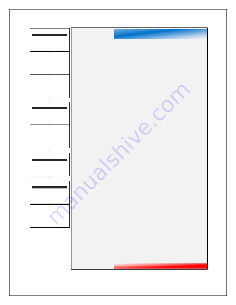
Data From (certain menu items only show up depending on the input type)
o
Source
determines the type of sensor installed in the detector. E.g. bridge,
electrochemical, etc.
o
Remote Sensor
set to Yes indicates that the sensor is installed remotely with Remote
sensor option.
o
Min and Max Raw
set the range of the input to the A/D converter. Normally set to
800/4000. Useful when the sensor’s output doesn’t provide a full range signal.
o
Remote ID
is where the Modbus slave’s ID number is entered
o
Alias
is the register number which defines the location of the variable representing the
input value of the Modbus data received through the communication ports
o
Interface
assigns which communication port the Modbus slave is connected to and the
detector will get its data from
o
Filter (second)
sets the number of seconds over which samples are averaged
o
Byte Order
determines WORD and BYTE alignment of data at the remote Modbus
transmitter when sending this 4-byte IEEE floating point values
o
Polarity
determines the polarity of the sensor
o
Heater
Enabled
determines if the sensor heater is turned on or off
o
Heat (degC)
is the thermostat setting of the sensor
o
Set
Voltage
set’s the voltage being supplied to bridge type sensors
o
Set
Balance
adjusts the balance of a catalytic bead sensor and must only be adjusted
with ZERO gas on the sensor.
o
Set
PGA
is the adjustment that matches the input signal range to the detectors input
signal conditioning circuits.
o
Marker
used to detect special modes of operation from analog inputs, which some
monitors use to indicate special modes of operation, such as calibration mode
Configure
o
Tag
is a 16-character ASCII field typically used to describe the monitored point by user
tag number or other familiar terminology.
o
E. Units
or engineering units may have up to 10 ASCII characters, and is usually factory
configured based on sensor type.
o
Zero
defines the reading to be displayed when the output is 4mA (0%)
o
Span
defines the reading to be displayed when 20mA (100%) is the output.
o
Decimal Points
sets the resolution of the displayed reading, and may best to zero, one
or two.
o
Block Negative
blocks negative values from being display (Displays 0).
o
Deadband (%)
allows forcing low values to continue to read zero. This is useful when
there are small amounts of background gases that cause fluctuating readouts above
zero. The highest amount of Deadband allowed is 5%. Note: Deadband affects all
outputs as well as the local reading.
o
Warmup (m)
defines the time allotted for sensor warmup. During this time output s will
be held at a zero value and relays will stay in their normal state.
o
Cal Purge (m)
determines the amount of time the transmitter will stay in calibration
mode after calibration is complete as the sensor returns to normal state.
Calibration
o
Zero Setpoint
is set to the zero value.
o
Span Setpoint
is set to the calibration gas value, typically 50% of full scale.
o
Cal Gain
reflects the change made when calibrating.
o
Gain Offset
reflects the change made when calibrating.
o
Gain Unity
is to reset the Gain and Offset back to default (1 and 0 respectively)
o
Calibrate
is used to calibrate sensors.
Temp Comp
allows the user to adjust the gain and offset that is applied to sensors to
compensate for temperature drift. Factory supplied sensors are preprogrammed with
these values which are automatically uploaded from the Smart Sensor.
Содержание 10-0517
Страница 4: ...UM 1096 Revision A III Drawings 44...
Страница 10: ...UM 1096 Revision A 5 Figure 2 Remote Sensor Enclosure Mounting Dimensions...
Страница 26: ......
Страница 49: ...UM 1096 Revision A 44 Appendix 9 Drawings Drawings Figure 13 Mounting Dimensions...
Страница 50: ...UM 1096 Revision A 45 Figure 14 10 0517 CPU Board Figure 15 10 0533 I O Board...
Страница 51: ...UM 1096 Revision A 46 Figure 16 10 0532 Modbus Relay Board...


