UM-1096
Revision A
6
3.3
Power and Analog Outputs Wiring
WARNING
: Qualified personnel should perform the installation according to applicable
electrical codes, regulations and safety standards. Ensure correct cabling and sealing
fitting practices are implemented. Do not aim the sensor pointing upward.
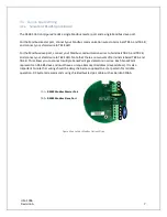
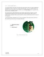
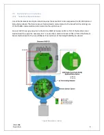
Modular design simplifies the installation of the SensePoints. A top display assembly is mounted with
captive thumbscrews and is easily removed to access field-wiring terminals. Option boards mount to the
back of the display assembly, and power, input and output wires mount to the power supply board.
3.3.1
110-230VAC @15W Power Wiring
The SensePoint is powered by a 110-230VAC @ 15Watt power supply. Which has a full range AC Input
along with short circuit, overload, over voltage and over temperature protections. The SensePoint can
be ordered with the optional 2.3M AC power cord for ease of wiring and installation.
3.3.2
4-20mA Output Wiring
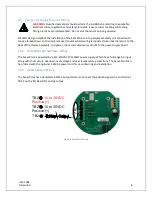
The SensePoint has a dedicated 4-20mA output terminal. Connect the 4-20mA signal wire to terminal
TB2.5 on the I/O Board for analog output.
Figure 3 SensePoint Wiring
TB
2
TB2.
-10 to 30VDC
Positive (+)
TB2. -10 to 30VDC
Positive (+)
TB2. -
Содержание 10-0517
Страница 4: ...UM 1096 Revision A III Drawings 44...
Страница 10: ...UM 1096 Revision A 5 Figure 2 Remote Sensor Enclosure Mounting Dimensions...
Страница 26: ......
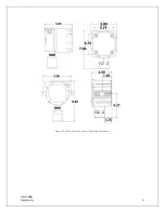
Страница 49: ...UM 1096 Revision A 44 Appendix 9 Drawings Drawings Figure 13 Mounting Dimensions...
Страница 50: ...UM 1096 Revision A 45 Figure 14 10 0517 CPU Board Figure 15 10 0533 I O Board...
Страница 51: ...UM 1096 Revision A 46 Figure 16 10 0532 Modbus Relay Board...


