


5
Manual No. 016-0230-044 Rev. F
63
ULTRAGLIDE
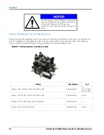
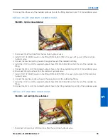
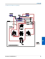
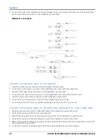
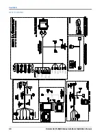
FIGURE 13. Machine’s Boom Function Cables
11. Locate the machine boom function coils near the machine’s hydraulic valve.
12. Disconnect the connector from the machine’s left tilt up coil.
13. Install the boom sense adapter cables (P/N 115-0171-546) between the coil and to the machine’s coil connector.
14. Connect the remaining boom sense adapter cables between the left tilt down, right tilt up, and right tilt down
coils and to the coil connectors.
15. On the harness cable, locate the left solenoid sense connectors.
16. Isolate the connector labeled up and connect it to the left tilt up coil via the installed boom sense adapter
cable.
17. Connect the other down left solenoid sense connector to the left tilt down coil via the installed boom sense
adapter cables.
18. Connect the right solenoid sense connectors to the machine’s right tilt up and right tilt down coils via the
installed boom sense adapter cables.
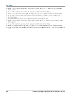
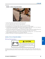
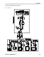
INSTALL CENTER RACK CONTROL
1. Locate the upper and lower boom hoist up coils near the machine’s hydraulic valve.
2. Disconnect the cable connector from the lower boom hoist up coil.
NOTE:
This is the boom hoist up coil that points towards the machine cab.
3. Install a center rack control boom sense adapter cable (P/N 115-0230-039) on the lower boom hoist up coil.
4. Connect one of the male ends of the power splitter cable (P/N 115-0230-070) to the installed boom sense
adapter cable.
5. Connect the female end of the power splitter cable to the cable removed from the lower boom hoist up coil.
6. Disconnect the cable connector from the upper boom hoist up coil.
NOTE:
Use cable ties to tie-off this connector. It is not used in the AutoBoom system.
7. Connect the remaining male end of the power splitter cable to the upper boom hoist up coil.
8. Disconnect the connector from the boom hoist down coil.
9. Install a center rack control boom sense adapter cable (P/N 115-0230-039)
between the coil and the cable
connector.
10. Connect the ends of the installed boom sense adapter cable (P/N 115-0230-039) on the lower boom hoist up
coil to the Center Up Sense and Control connectors of the AutoBoom harness (P/N 115-0230-045 or P/N 115-
0230-085).
Содержание RoGator 64 Series
Страница 9: ...2 Manual No 016 0230 044 Rev F 5 INTRODUCTION ...
Страница 10: ...CHAPTER 2 6 RoGator 64 74 86 SS Series AutoBoom Installation Manual ...
Страница 21: ...3 Manual No 016 0230 044 Rev F 17 POWERGLIDE POWERGLIDE HYDRAULIC SCHEMATIC ...
Страница 40: ...CHAPTER 4 36 RoGator 64 74 86 SS Series AutoBoom Installation Manual POWERGLIDE PLUS HYDRAULIC SCHEMATIC ...
Страница 47: ...Manual No 016 0230 044 Rev F 43 POWERGLIDE PLUS POWERGLIDE PLUS WIRING SCHEMATIC GEN I CABLING ...
Страница 48: ...CHAPTER 4 44 RoGator 64 74 86 SS Series AutoBoom Installation Manual GEN II CABLING ...
Страница 61: ...5 Manual No 016 0230 044 Rev F 57 ULTRAGLIDE ULTRAGLIDE HYDRAULIC SCHEMATIC ...
Страница 71: ...Manual No 016 0230 044 Rev F 67 ULTRAGLIDE ULTRAGLIDE WIRING SCHEMATIC GEN I CABLING ...
Страница 72: ...CHAPTER 5 68 RoGator 64 74 86 SS Series AutoBoom Installation Manual GEN II CABLING ...
Страница 75: ...6 Manual No 016 0230 044 Rev F 71 REPLACEMENT PARTS SENSORS ...
Страница 76: ...CHAPTER 6 72 RoGator 64 74 86 SS Series AutoBoom Installation Manual ...