C
HAPTER
4
40
RoGator 64/74/86/SS Series AutoBoom Installation Manual
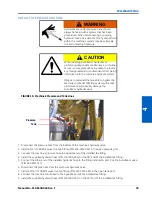
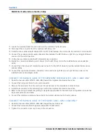
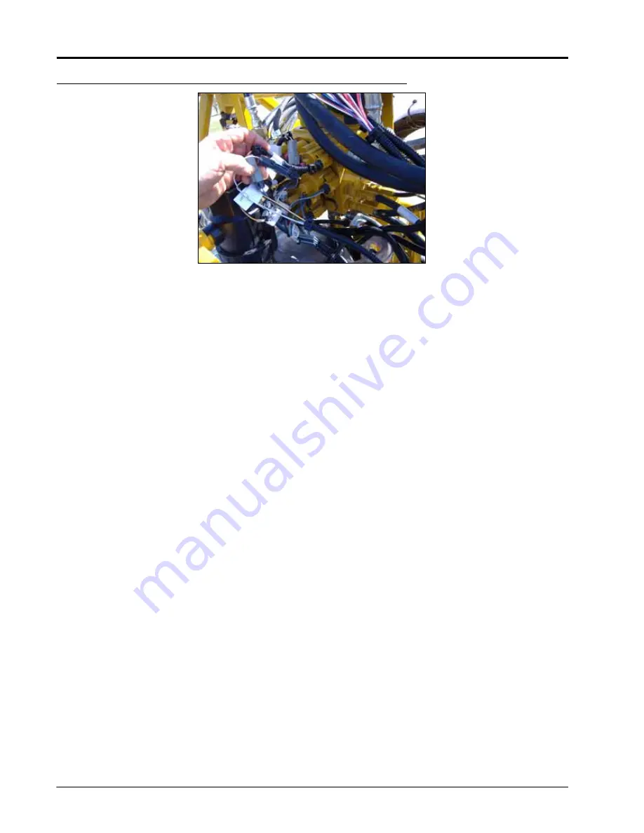
FIGURE 16. Machine’s Boom Function Cables
11. Locate the machine boom function coils near the machine’s hydraulic valve.
12. Disconnect the connector from the machine’s left tilt up coil.
13. Install the boom sense adapter cables (P/N 115-0171-546) between the coil and to the machine’s coil connector.
14. Connect the remaining boom sense adapter cables between the left tilt down, right tilt up, and right tilt down
coils and to the coil connectors.
15. On the harness cable, locate the left solenoid sense connectors.
16. Isolate the connector labeled up and connect it to the left tilt up coil via the installed boom sense adapter
cable.
17. Connect the other down left solenoid sense connector to the left tilt down coil via the installed boom sense
adapter cables.
18. Connect the right solenoid sense connectors to the machine’s right tilt up and right tilt down coils via the
installed boom sense adapter cables.
CONNECT THE HARNESS CABLE TO THE IMPLEMENT EXTENSION TEE - GEN II CABLE ONLY
1. Route the harness cable (P/N 115-0230-085) toward the implement extension tee cable.
2. Connect the harness cable to the to node connector.
3. Remove the terminator from the machine’s chassis harness or the standalone console harness.
4. Install the terminator on the remaining open end of the implement extension tee cable.
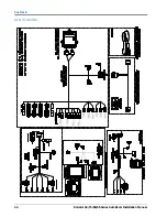
5. Refer to the wiring schematic (beginning on page 43) appropriate for the machine’s configuration to route the
implement extension tee cable.
6. Connect the implement extension tee cable to the location determined in the step above.
CONNECT THE HARNESS CABLE TO THE POWER CABLE - GEN I CABLE ONLY
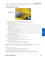
1. Route the harness cable (P/N 115-0230-045) toward the machine’s cab.
2. Connect the harness cable to the power cable (P/N 115-0230-007).
3. Tighten the connector screw cap to secure the connection.
Содержание RoGator 64 Series
Страница 9: ...2 Manual No 016 0230 044 Rev F 5 INTRODUCTION ...
Страница 10: ...CHAPTER 2 6 RoGator 64 74 86 SS Series AutoBoom Installation Manual ...
Страница 21: ...3 Manual No 016 0230 044 Rev F 17 POWERGLIDE POWERGLIDE HYDRAULIC SCHEMATIC ...
Страница 40: ...CHAPTER 4 36 RoGator 64 74 86 SS Series AutoBoom Installation Manual POWERGLIDE PLUS HYDRAULIC SCHEMATIC ...
Страница 47: ...Manual No 016 0230 044 Rev F 43 POWERGLIDE PLUS POWERGLIDE PLUS WIRING SCHEMATIC GEN I CABLING ...
Страница 48: ...CHAPTER 4 44 RoGator 64 74 86 SS Series AutoBoom Installation Manual GEN II CABLING ...
Страница 61: ...5 Manual No 016 0230 044 Rev F 57 ULTRAGLIDE ULTRAGLIDE HYDRAULIC SCHEMATIC ...
Страница 71: ...Manual No 016 0230 044 Rev F 67 ULTRAGLIDE ULTRAGLIDE WIRING SCHEMATIC GEN I CABLING ...
Страница 72: ...CHAPTER 5 68 RoGator 64 74 86 SS Series AutoBoom Installation Manual GEN II CABLING ...
Страница 75: ...6 Manual No 016 0230 044 Rev F 71 REPLACEMENT PARTS SENSORS ...
Страница 76: ...CHAPTER 6 72 RoGator 64 74 86 SS Series AutoBoom Installation Manual ...

