


C
HAPTER
4
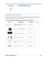
30
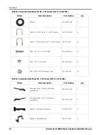
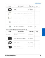
RoGator 64/74/86/SS Series AutoBoom Installation Manual
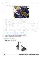
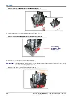
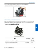
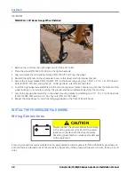
FIGURE 3. Port Plugs Removed from the AutoBoom Valve
3. Use an Allen wrench to remove the plugs from ports 3A and 3B.
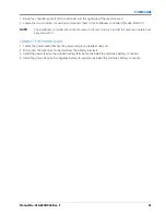
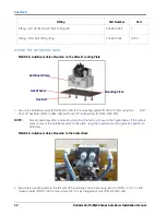
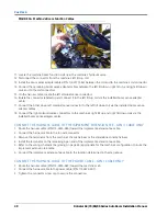
FIGURE 4. Orifice Fitting Removed from the AutoBoom Valve
4. Remove the orifice fittings from ports 3A and 3B.
IMPORTANT:
Tip the AutoBoom valve on its side and use the Allen wrench to remove the orifice from the cavity, taking
care not to let the fitting fall into the valve.
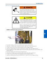
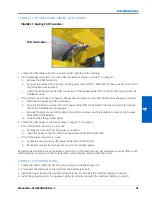
FIGURE 5. Port Plug Reinstalled on the AutoBoom Valve
Orifice Fitting
Removed - Keep
for Future Use
Содержание RoGator 64 Series
Страница 9: ...2 Manual No 016 0230 044 Rev F 5 INTRODUCTION ...
Страница 10: ...CHAPTER 2 6 RoGator 64 74 86 SS Series AutoBoom Installation Manual ...
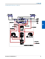
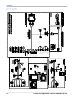
Страница 21: ...3 Manual No 016 0230 044 Rev F 17 POWERGLIDE POWERGLIDE HYDRAULIC SCHEMATIC ...
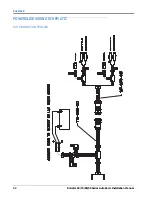
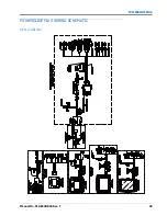
Страница 40: ...CHAPTER 4 36 RoGator 64 74 86 SS Series AutoBoom Installation Manual POWERGLIDE PLUS HYDRAULIC SCHEMATIC ...
Страница 47: ...Manual No 016 0230 044 Rev F 43 POWERGLIDE PLUS POWERGLIDE PLUS WIRING SCHEMATIC GEN I CABLING ...
Страница 48: ...CHAPTER 4 44 RoGator 64 74 86 SS Series AutoBoom Installation Manual GEN II CABLING ...
Страница 61: ...5 Manual No 016 0230 044 Rev F 57 ULTRAGLIDE ULTRAGLIDE HYDRAULIC SCHEMATIC ...
Страница 71: ...Manual No 016 0230 044 Rev F 67 ULTRAGLIDE ULTRAGLIDE WIRING SCHEMATIC GEN I CABLING ...
Страница 72: ...CHAPTER 5 68 RoGator 64 74 86 SS Series AutoBoom Installation Manual GEN II CABLING ...
Страница 75: ...6 Manual No 016 0230 044 Rev F 71 REPLACEMENT PARTS SENSORS ...
Страница 76: ...CHAPTER 6 72 RoGator 64 74 86 SS Series AutoBoom Installation Manual ...