14
ENGLISH
Introduction
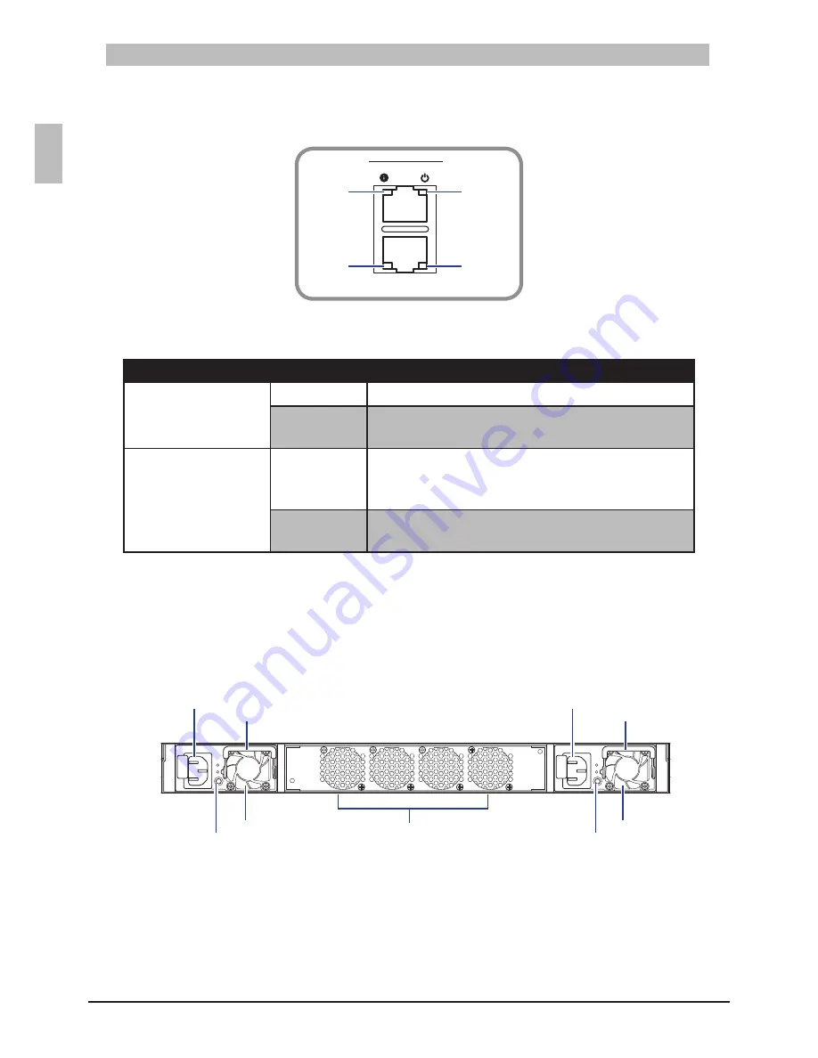
Console and Management Port LEDs
2.1.1.2
Console and Management Port LEDs
Figure 2-3:
45
46
47
48
41
42
43
44
39
40
37
38
35
36
33
34
31
32
29
30
27
28
25
26
23
24
21
22
19
20
17
18
15
16
13
14
11
12
9
10
7
8
5
6
3
4
1
2
MGMT
CON
T3040-LY3
Status
Speed
Power
Link/Activity
Console and Management Port LEDs
Table 2-2:
LED
Description
Console Port
Status
Orange
: Always on when booting sequence completes.
Power
Green
•
: Power is on.
Off
•
: Power is off.
Management Port
Speed
Yellow
•
: A valid 1G network link is established.
Green
•
: A valid 100Mbps network link is established.
Off
•
: A valid 10Mbps network link is established.
Link/Activity
Green
•
: A valid network link is established.
Flashing Green
•
: Network activity in progress.
Rear Panel
2.2
The following figure shows the rear panel of the switch.
Rear Panel View
Figure 2-4:
Fan Assembly
Handle
PSU2
PSU1
AC Power Connector
(with Plug Retainer)
Handle
AC Power Connector
(with Plug Retainer)
PSU2 LED
PSU1 LED
The switch has two Power Supply Units (PSU) and four fan modules. The fan modules can be built in
as back-to-front or front-to-back depending on customer requirements.
The AC power connector is a standard three-pronged connector. The switch automatically adjusts its
power setting to any supply voltage in the range from 100~240 VAC at 50~60 Hz.
When the PSU is connected to the power source, the PSU LED lights green.


