20
ENGLISH
Hardware Installation
Connect to Power
3.3
The switch has two Power Supply Units (PSU). Each PSU has an AC power connector. Depending on
your needs, you may opt to use one or both PSUs at a time.
To connect the switch to a power source, do the following:
Connect one end of the AC power cord to an AC power connector.
1.
If you want to use two PSUs, connect another strip of AC power cord to the other AC power
2.
connector. Otherwise, skip this step.
Connect the other end(s) of the AC power cord(s) to grounded power outlet(s).
3.
The switch has no power button. Once an AC power cord is connected to a power outlet, the switch
power is turned on. The Power LED lights green.
Check the Installation
3.4
Check the following pointers to inspect the installation:
Is the switch securely installed and stable?
•
Is/Are the AC power cord(s) properly connected to the power outlet(s)?
•
Is the Power LED (on the Console port) lit green?
•
Connect Equipment
3.5
You can connect equipment to the switch through the 10GBASE-T and SPF+ ports.
10GBASE-T Port
3.5.1
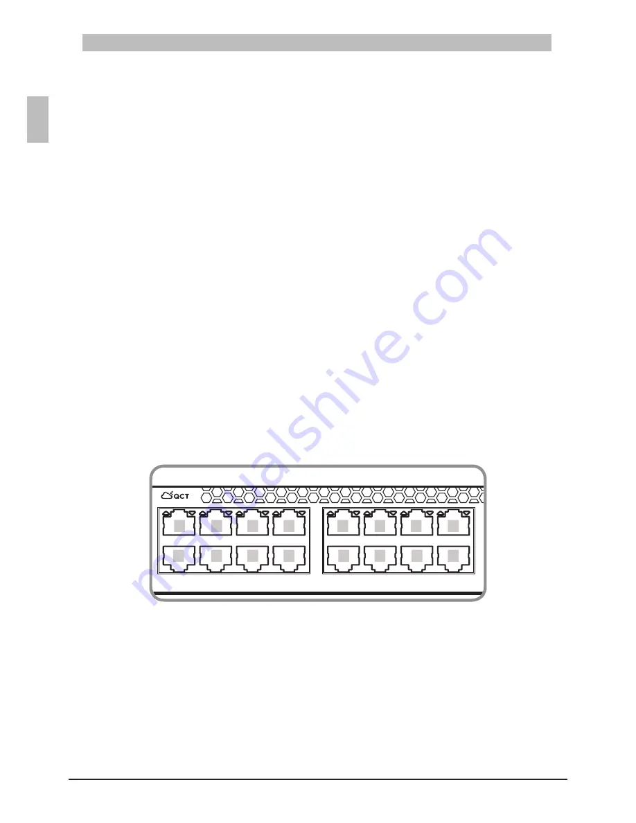
The switch has 40-10GBASE-T ports which are numbered and have their corresponding 10GBASE-T
port LEDs. The upper row ports are odd numbered (i.e. Port 1, Port 3, Port 5, and so on). The lower
row ports are even numbered (i.e. Port 2, Port 4, Port 6, and so on). See illustration below.
10GBASE-T Port Numbering
Figure 3-4:
45
46
47
48
41
42
43
44
39
40
37
38
35
36
33
34
31
32
29
30
27
28
25
26
23
24
21
22
19
20
17
18
15
16
13
14
11
12
9
10
7
8
5
6
3
4
1
2
MGMT
CON
T3040-LY3
1
3
5
7
9
11
2
4
6
8
10
12
14
16
13
15


