40
41
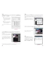
PICTURE 3-31
PICTURE 3-32
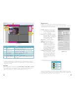
Real-Time Monitor
Live monitoring and recorded video playback takes place in the Real-Time Monitor section of
the window. The number of screens being viewed at once is set with the Image View Options
at the bottom of the screen (described below), but at any time, you can double-click on any
channel in multi-view mode to make it a single-screen view. Double-clicking on the screen will
return it to its place in the multi-view display.
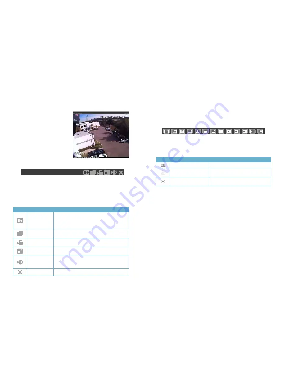
At the top of each channel’s video display, there is a set of data and a set of six function
buttons.
The data in the upper left shows the device’s IP address, the channel and the stream rate for
that channel as well as which stream it is using.
The function buttons allow you to perform operations within the display. Each button will only
affect the channel it is attached to. Other channels will not be affected.
Symbol Button
Function
Digital Zoom
Select this button (it will highlight in white) and then click
and drag within the video image to zoom in on that
section. Clicking on the button again will return you to the
original view.
Multi-Screen/
Single Screen View
This will switch between a multi-screen or single screen
view of that video.
Local Record
When this button is selected, you will begin recording it to
your computer
Snapshot
This will take still images of the video which will be saved
according to your settings in Pic Path
Audio
Turns audio on or off if this channel has audio connected
to it. This does not have any relationship to the computer’s
audio
Close Video
Ends the video display for that channel
20.2.3.78-1-585Kbps S2
Image View Options
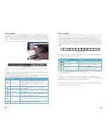
This row of buttons along the bottom of the Real-Time Monitor area allow you to set how you
will view the video feeds in addition to how many screens will be displayed simultaneously.
Some settings will display more channels than a single NVR can connect to, but if you are
controlling multiple NVRs of the same type using Q-See’s Centralized Management System
(PSS) you will be able to display the signals from multiple NVRs simultaneously. When you do
not have as many cameras as channels displayed, the empty channels will remain grayed out
and display “No Signal” in the upper left where the IP, bitrate and channel data would normally
appear.
The first three buttons in the row deal with image quality and size, while the remaining buttons
will configure the display to show 1-36 images.
PICTURE 3-33
Symbol Button
Function
Image Quality
This raises or lowers the quality of the image
Latency/Fluency
Allows you to prioritize image quality versus
smoothness of the video
Full Screen
Selecting this will expand the entire display to fill
the full screen, hiding all the controls.
In the case of the
Image Quality
and
Latency/Fluency
buttons, only the channel highlighted
in green will be affected.
In multi-screen mode, a channel can be clicked and dragged to another location. This is
useful in those modes where one or two screens are larger than the others. The channel being
replaced will move to the old location of the one that was moved.
Double clicking on a channel will bring that to single screen mode. Double clicking on it again
will return to the previous multi-channel format.


