DRIVESYSTEMS
HOLLOW SHAFT WITH
SHRINK DISC
RETAIN FOR FUTURE USE
1. Shrink disc design concept
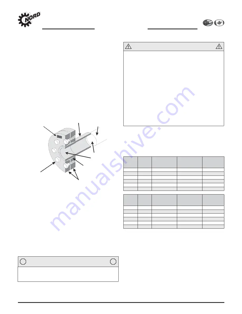
A shrink disc option is adaptable to many NORD hollow-bore
reducers. The shrink disc applies a high-capacity, zero back-
lash, interference fi t to the driven machine shaft. The dou-
ble tapered inner ring converts most all of the screw clamp-
ing load into radial contact pressure, as the outer clamping
discs are pulled together by proper tightening of the locking
screws. As the inner ring is contracted, the clearance between
the customer solid shaft and reducer shaft is absorbed.
• In their relaxed state, shrink discs provide a generous
assembly clearance, thus eliminating the typical assembly
and disassembly challenges of using interference fi ts.
• Shrink discs also reduce solid machine shaft stresses by
eliminating the need for shaft keys and keyways.
• When properly applied, high shrink fi ts help eliminate
shaft fretting corrosion and allow for easier shaft mounting
and
dismounting.
TAG:
Shrink Disc Type
& Bolt Torque
Reducer Shaft
Customer Solid Shaft
Locking Screws
Outer Clamping
Discs
Inner Ring
(Ferrule)
Do Not
Lubricate!!
2. Solid (machine) shaft design guidelines
Always use a solid shaft material of adequate strength and
apply proper shaft fi ts in order to establish adequate clamp-
ing force during assembly and assure proper shaft release
during disassembly.
• Use solid shaft material with yield strength of at least
52,260 psi (360 N/mm
2
).
• The solid machine shaft should be machined according to
ISO 286-2, Class h6 fi t tolerances, with a shaft fi nish of 125
micro inches (3.2 μm) or smoother, per Table 1.
• The solid machine shaft must extend the full length of the
reducer hollow shaft.
STOP
HARMFUL SITUATION
STOP
Contact NORD when using a shrink disc in an application
where the shrink disc connection must simultaneously
transmit torque and thrust.
3. Safety
WARNING
• The supporting solid shaft or driven machine shaft must
be of adequate size and strength to withstand normal
operating loads and peak loads without damage to
itself or any of the system components.
• The transmissible torque and the gripping capacity of
the shrink disc may be reduced if shaft tolerances or
clearances are larger than specifi ed.
• Excessive tightening torque can result in permanent
deformation of the inner ring and the reducer hollow
bore, making disassembly very diffi cult. Do not over
tighten the shrink disc to compensate for excessive
clearance between the machine shaft and reducer bore.
• Observe the published ratings and safety factors
for both the reducer and shrink disc. Overload
conditions or excessively high torque can cause the
shrink disc connection to slip. In extreme cases localized
galling or welding of components may occur.
4. Shrink disc shaft tolerances
Recommended solid shaft tolerances and reducer bore toler-
ances are shown in the table below.
Table 1: Shrink disc shaft tolerances
Above &
Including
ø [in]
To &
Including
ø [in]
Solid Shaft
Tolerance
ø [in]
Reducer Bore
Tolerance
ø [in]
Max. Assembly
Clearance
[in]
0.7500
1.1250
+0.0000 / -0.0005
+0.0008 / -0.0000
0.0013
1.1250
1.9375
+0.0000 / -0.0006
+0.0009 / -0.0000
0.0015
2.0000
3.1250
+0.0000 / -0.0007
+0.0011 / -0.0000
0.0018
3.1875
4.6875
+0.0000 / -0.0008
+0.0013 / -0.0000
0.0021
4.7500
7.0625
+0.0000 / -0.0009
+0.0015 / -0.0000
0.0024
7.1250
7.5000
+0.0000 / -0.0011
+0.0018 / -0.0000
0.0029
Above
ø [mm]
To &
Including
ø [mm]
Solid Shaft
Tolerance
ø [mm]
Reducer Bore
Tolerance
ø [mm]
Max. Assembly
Clearance
[mm]
18
30
+0.000 / -0.013
+0.021 / -0.000
0.034
30
50
+0.000 / -0.016
+0.025 / -0.000
0.041
50
80
+0.000 / -0.019
+0.030 / -0.000
0.049
80
120
+0.000 / -0.022
+0.035 / -0.000
0.057
120
180
+0.000 / -0.025
+0.040 / -0.000
0.065
180
190
+0.000 / -0.029
+0.046 / -0.000
0.075
Shaft/bore tolerances per ISO 282-6, Class h6/H7.
Solid shaft fi nish should be 125 micro inches (3.2
micro meters) or smoother.
U10290 - 1 of 2
www.nord.com/docs
02.11.13
NORD Gear Corporation
Toll Free in the United States: 888.314.6673
NORD Gear Limited
Toll Free in Canada: 800.668.4378
Содержание Pulsalube 8 GS Ultra
Страница 8: ......
Страница 18: ......
Страница 20: ......
Страница 36: ......
Страница 38: ......
Страница 42: ......
Страница 48: ......
Страница 50: ......
Страница 53: ......
Страница 54: ......
Страница 55: ......
Страница 56: ......
Страница 61: ......
Страница 62: ......
Страница 64: ......
Страница 86: ......
Страница 87: ......
Страница 88: ......
Страница 89: ...XVJDEH LVVXH RNXPHQW GRFXPHQW 20 6 XV ODWW VKHHW 6SDUH SDUWV 6SDUH SDUWV OLVW 6HFWLRQDO GUDZLQJ DQG SDUWV OLVW...
Страница 90: ......
Страница 93: ......
Страница 94: ......
Страница 96: ......
Страница 98: ......
Страница 100: ......
Страница 110: ......
Страница 113: ......
Страница 114: ......
Страница 116: ......
Страница 118: ......
Страница 122: ......
Страница 126: ......


