121
6 .2 .5 XY View
Before measurement begins, the laser beam must be adjusted such that it strikes
the detector surface. The beam should strike the detector as close to the center as
possible. To facilitate adjustment, the height of the sensor and the laser should be
aligned, and the brackets are rotationally aligned.
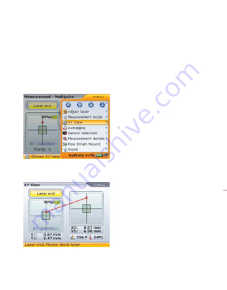
The option ‘XY View’ can be activated to help meet the requirement mentioned
above.
To access the “XY View” screen, press
q
while in the measurement screen. Use
g
/
f
to highlight the context menu item ‘XY View’.
Confirm selection by pressing
e
. The laser beam position on the two detector
planes is displayed.
Additional ‘XY View’ capabilities include the setting of the XY coordinates as a
reference value. To access this option, press
q
while in the “XY View” screen above.
Displayed are the absolute
X,Y coordinates of the laser
beam on the two detector
surfaces, the angle at which
the sensor is currently
positioned on the shaft and
the sensor temperature.
XY View
Содержание OPTALIGN smart RS5 BT
Страница 10: ...OPTALIGN smart RS5 BT handbook 10 Page intentionally left blank ...
Страница 16: ...OPTALIGN smart RS5 BT handbook 16 This page intentionally left blank ...
Страница 28: ...OPTALIGN smart RS5 BT handbook 28 Page intentionally left blank ...
Страница 38: ...OPTALIGN smart RS5 BT handbook 38 This page intentionally left blank ...
Страница 112: ...OPTALIGN smart RS5 BT handbook 112 This page intentionally left blank ...
Страница 174: ...OPTALIGN smart RS5 BT handbook 174 This page intentionally left blank ...
Страница 194: ...OPTALIGN smart RS5 BT handbook 194 This page intentionally left blank ...


