502 069 02
50/79
Power Monitor, PD 3260
Manual
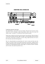
Synchronous generator connection:
The diagram shows a system where the Power Monitor Channel and the Generator Switch
Channel are used for controlling a digital output channel to drive a relay. For systems with
thyristor output, see chapter 7.1: Connections to Thyristor Switch Channel.
When using a synchronous generator, the generator speed is measured using a voltage transformer
connected to the generator terminal UGEN. The primary of the transformer must be connected
between the L1 and L3 lines in a similar way to the line voltage transformer between L1 and L3,
but on the other side of the switching element.
Only the voltage transformers connected between L1 and L3 on the power line and at the
generator, are nessecary inputs for the synchronous generator switch function. Additional current
and voltage transformers may be optionally connected, if Power Monitor Channel functions are
required. It is recommended that unused voltage inputs are connected to the 24V- terminal,
otherwise noise at the inputs may generate errors.


