


Helios PD2-6080/PD2-6081 Modbus
®
Scanners
Instruction Manual
5
Analog Output Source Programming (
) ........................................... 66
Programmable Function Keys User Menu (
) ....................................... 68
) ............................................................................ 69
) ......................................................................... 69
).................................................................................... 69
) ............................................................................... 70
Recalibrating the Analog Input Channels (Ch-A & Ch-B) ............................ 70
) .............................................................................. 72
Determining Software Version..................................................................... 72
Reset Scanner to Factory Defaults ............................................................. 72
Maximum/Minimum Readings ...................................................................... 73
Table of Figures
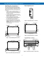
Figure 1. Scanner Mounting Holes Location ................................................... 14
Figure 2. Scanner Mounting Holes Dimensions ............................................. 14
– Side View..................................................... 14
Figure 4. Scanner Dimensions - Front View .................................................... 14
Figure 5. Conduit Holes Location
– Bottom View ........................................... 14
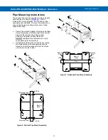
Figure 6. Vertical Pipe Mount Assembly.......................................................... 15
Figure 7. Horizontal Pipe Mount Assembly ..................................................... 15
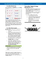
Figure 8. Transmitter Supply Voltage Selection ............................................. 17
Figure 9. PD2-6080/1-6H0 / 7H0 Connectors Label ......................................... 18
Figure 10. PD2-6080/1-6H7 / 7H7 Connectors Label ....................................... 18
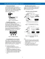
Figure 13. Five-Wire RS-485 Connections ....................................................... 19
Figure 14. Three-Wire RS-485 Multi-Drop Connections ................................. 19
Figure 15. Connections for RS-485 Connector to Serial Converter .............. 20
Figure 16. Three-Wire RS-485 Connection ...................................................... 20
Figure 17. Digital Input and Output Connections ........................................... 20
Figure 20. AC and DC Loads Protection .......................................................... 21
Figure 21. Low Voltage DC Loads Protection ................................................. 21
Figure 22. 4-20 mA Output Connections ......................................................... 21
Figure 23. Analog Output Supply Powering Other Devices........................... 21
Figure 24. Meter to PDA2364-MRUE Control Station Connection ................. 22
Figure 26. Transmitters Powered by Internal Supply ..................................... 22
Figure 27. Transmitter Powered by Ext. Supply or Self-Powered ................. 22


