Helios PD2-6080/PD2-6081 Modbus
®
Scanners
Instruction Manual
41
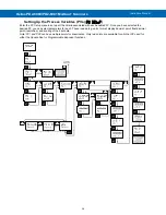
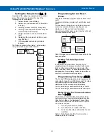
Setting the Tags (
tAg
) & Units
(
units
)
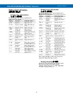
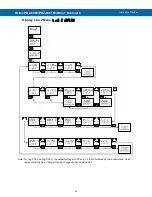
Each PV can be setup with its own tag and units. See
the flow charts on the previous pages to access the
display menu to show the tag or toggling tag & units.
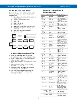
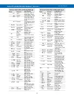
The engineering units and custom tags can be set
using the following 7-segment character set:
Display
Character
Display
Character
0
0
k
K
1
1
l
L
2
2
n m
m
3
3
n
n
4
4
O
O
5
5
o
o
6
6
p
P
7
7
q
q
8
8
r
r
9
9
s
S
A
A
t
t
b
b
u
u
C
C
v
V
c
c
u w
w
d
d
x
X
e
E
y
Y
f
F
z
Z
g
G
-
-
9
g
/
/
H
H
[
]
h
h
]
[
I
I
=
=
I
i
!
Degree(<)
j
J
Space
Notes:
1.
Degree symbol represented by (<) if programming
with ScanView.
2.
The letters “m” and “w” use two 7-segment LEDs
each; when selected the characters to the right are
shifted one position.
3. Press and hold up arrow to auto-scroll the
characters in the display.
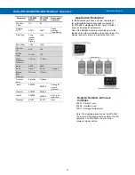
Application Example 1
In this application we have a system consisting of
(4) multivariable tank level gauges connected to
(2) PD2-6080 Mobus scanners displaying Product
Level, Interface Level, and Average Temperature.
One of the Modbus Scanners is located next to the
tanks and the other is located in the control room.
Register Numbers & Process
Variables
30001 - Product Level
30003 - Interface Level
30017 - Average Temperature
The following table shows the system setup for a
typical multivariable level gauge, one PD2-6080
Master, and one PD2-6080 Snooper:
Parameter
PD2-6080
Master
PD2-6080
Snooper
Description/
Comment
Mode
Master
Snooper
PV1 Slave
ID
1
1
Function
Code
04
04
Register
PV1
30001
30001
Tank 1
Product
Level
Data Type
Long
integer
Binary,
Signed
Long
Byte Order
1234
1234
PV2 Slave
ID
1
1
Function
Code
04
04
Register
PV2
30003
30003
Tank 1
Interface


