background image

Helios PD2-6080/PD2-6081 Modbus

®

 Scanners 

Instruction Manual 


28 

Display Functions & Messages 

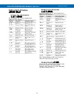
Display


Parameter 

Action/Setting 
Description 

  d-Inty 

Display 
Intensity 

Display Intensity 

 relay 

Relay Setup 

Enter 

Relay Setup 

menu 

  assign 

Assign 
Relay 

Assign Relay menu 

   Relay 1


Relay 1-4


Assign Relay 1-4 

    PV 1 

PV 1-16 

Map Relay to PV 1-16 

    nm-pV 

Multiple PVs 

Map Relay to Multiple 
PVs 

  Rly 1


Relay 1-4


Relay 1-4 

   act 1


Relay 
Action 1-4


Assign Relay Action for 
relays 1-4 

 Auto 

Automatic 

Set relay for automatic 
reset 

 A-nman 

Auto-
manual 

Set relay for auto or 
manual reset any time 

 LatCH 

Latching 

Set relay for latching 
operation 

 Lt-CLr 

Latching-
cleared 

Set relay for latching 
operation with manual 
reset only after alarm 
condition has cleared 

 Altern 

Alternate 

Set relay for pump 
alternation control 

 SAnmpl 

Sample 

Set relay for sample 
time trigger control 

 Off 

Off 

Turn relay off 

  FaiLSF 

Fail-safe 

Enter 

Fail-safe 

menu 

FLS 1


Fail-safe 1 


Set relay 1-4 fail-safe 
operation 

 on 

On 

Enable fail-safe 
operation 

 off 

Off 

Disable fail-safe 
operation 

  DeLAY 

Delay 

Enter relay 

Time Delay 

menu 

DLY 1*


Delay 1*


*Enter relay 1-4 time 
delay setup 

 On 1 

On 1 

Set relay 1 On time 
delay 

 OFF 1 

Off 1 

Set relay 1 Off time 
delay 

  break 

Break 

Set relay condition if 
communication break 
detected 

No act 

No action 

Ignore break condition.  

No

 change in relay state 

when Communications 
Break detected. 

   On 

On 

Relay goes to alarm 
condition when break 
detected.  Relay turns 

on

 when 

Communications Break 
detected. 

   Off 

Off 

Relay goes to non-alarm 
condition when break 
detected.  Relay turns 

off

 when 

Communications Break 
detected. 

Display Functions & Messages 

Display


Parameter 

Action/Setting 
Description 

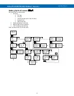
 Aout 

Analog 
output 

Enter the 

Analog Output


scaling menu 

  AOut 1*


Aout 
channel


Analog Output source 
channel 

Dis 1 

Display 1 

Program the first 

Display


value for the Analog 
Output. 

 Out 1 

Output 1 

Program the first 

Output


value that corresponds 
to the Display 

1

 value 

for the Analog Output. 
(e.g. 4.000 mA).   

Dis 2 

Display 2 

Program the second 

Display

 value for the 

Analog Output. 

 Out 2 

Output 2 

Program the second 

Output

 value that 

corresponds to the 
Display 

2

 value for the 

Analog Output. (e.g. 
4.000 mA).  (e.g. 20.000 
mA) 

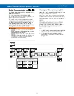
serial 

Serial 

Enter 

Serial

 menu 

 SCan.ID 

Scan ID 

Enter 

Scan ID

 of the 

meter being polled  
(1-247) 

 baud 

Baud Rate 

Select 

Baud Rate 

(Choices: 
300/600/1200/2400/480
0/9600/19,200) 
(Must match that of 
other devices)


 Tr dly 

Transmit 
Delay 

Enter 

Transmit Delay  

(Master’s delay must be 
greater than Snooper or 
slave devices)


 parity 

Parity 

Select 

Parity (Even, 

Odd, None 1-Stop, or 
None 2-Stop) 
(Must match that of 
other devices)


 t-byt 

Byte-to-byte 
Timeout 

Enter the timeout value 
allowed between 
received 

bytes

.


(This is used to fix 
communication 
problems with slow 
devices).


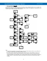
pass 

Password 

Enter the 

Password


menu 

Pass 1 

Password 1 

Set or enter Password 1 

Pass 2 

Password 2 

Set or enter Password 2 

Pass 3 

Password 3 

Set or enter Password 3 

 unloc 

Unlocked 

Program password to 
lock scanner 

 locd 

Locked 

Enter password to 
unlock scanner 

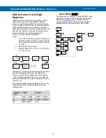
999999 

-99999 

Flashing 

Over/under range 
condition 


Содержание Helios PD2-6080

Страница 1: ...splay 1 8 46 mm Digits Readable up to 100 Feet 30 Meters Away 4 Relays with Interlocking Capability Isolated 4 20 mA Output Option Free PC Based On Board ScanView USB Programming Software SunBright Di...

Страница 2: ...om for complete details Registered Trademarks All trademarks mentioned in this document are the property of their respective owners 2021 Precision Digital Corporation All rights reserved FREE ScanView...

Страница 3: ...llation Overview 16 ScanView Software 16 ScanView Installation 16 ScanView Monitoring 17 ScanView Data Logging 17 Transmitter Supply Voltage Selection P P 17 Connections 18 Connectors Labeling 18 Powe...

Страница 4: ...6 Time Delay Operation 46 Relay Sampling Operation 46 Relay and Alarm Operation Diagrams 47 High Alarm Operation Set Reset 47 Low Alarm Operation Set Reset 47 High Alarm with Fail Safe Operation Set R...

Страница 5: ...6 Vertical Pipe Mount Assembly 15 Figure 7 Horizontal Pipe Mount Assembly 15 Figure 8 Transmitter Supply Voltage Selection 17 Figure 9 PD2 6080 1 6H0 7H0 Connectors Label 18 Figure 10 PD2 6080 1 6H7...

Страница 6: ...ce absolute difference average weighted average multiplication division minimum maximum draw ratio and concentration This is in addition to the input signal conditioning functions linear square root p...

Страница 7: ...D PD2LH3CB1 RYG Light Horn with Red Yellow Green Light Layers Button Mounted and Wired to Helios 1 Note 1 Specify MOD PD2LH model as a separate item on the order for the Helios to order the Light Horn...

Страница 8: ...ponse timeout timer Slave Snooper mode Time the scanner will wait for new data before going into break condition Slave mode Programming 0 disables the timeout the last value received will be displayed...

Страница 9: ...tion keys and digital inputs Non Volatile Memory All programmed settings are stored in non volatile memory for a minimum of ten years with or without power Power Options 85 265 VAC 50 60 Hz 90 265 VDC...

Страница 10: ...able exponent accuracy range 10 100 of calibrated span Temperature Drift 0 005 of calibrated span C max from 0 to 65 C ambient 0 01 of calibrated span C max from 40 to 0 C ambient Input Signal Conditi...

Страница 11: ...ys Programmable and independent for each relay Fail Safe Operation Programmable and independent for each relay Note Relay coil is energized in non alarm condition In case of power failure relay will g...
Страница 12: ...e reset relays and reset max min values See Function Keys Digital I O Available Settings on page 68 for a complete list of capabilities Channels 4 digital inputs 4 digital outputs Digital Input Logic...

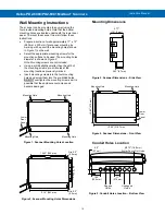
Страница 13: ...under the lower door panel and are accessible by removing the single securing screw Wires should be run through the knockout holes located on the bottom of the scanner see Figure 5 Conduit Holes Locat...

Страница 14: ...h of the mounting screws pre drill holes at the mounting locations previously marked Insert mounting screws into the four mounting holes and screw them into the pre drilled holes DO NOT overtighten th...

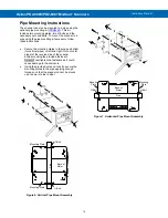
Страница 15: ...top and bottom for vertical pipes or left and right for horizontal pipes of the reverse side of the scanner enclosure using the provided fasteners DO NOT overtighten the fasteners as it could cause da...

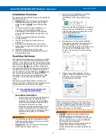
Страница 16: ...d of the provided USB cable to the scanner and the other end to the computer The computer will automatically install the driver software it needs to talk to the scanner Follow the on screen instructio...

Страница 17: ...t Data Log Start from the top menu bar The log file can be retrieved at any time by following the path C Program Files x86 PDC ScanView 1 00 Data Log Once Data Logging has begun the Configure Customiz...

Страница 18: ...l shows the location of all connectors available with the ordered configuration DO NOT connect any equipment to the RJ45 M LINK connector Otherwise damage will occur to the equipment and the meter DO...

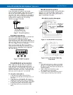
Страница 19: ...with 1 or 2 stop bits To change the meter address 1 Press and hold the Menu button for three seconds to access Advanced Features menu of the meter 2 Press Up arrow until Serial SEriaL menu is displaye...

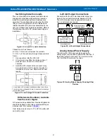
Страница 20: ...VDC terminal Digital output connections are made by wiring from the appropriate digital output terminal to the ground terminal Figure 17 Digital Input and Output Connections F4 Digital Input Connecti...

Страница 21: ...times the circuit voltage and forward current at least as large as the load current Figure 21 Low Voltage DC Loads Protection RC Networks Snubbers Available from Precision Digital RC networks are ava...

Страница 22: ...nel LED is on When the Interlock Contact is open the corresponding front panel LED flashes locked out the Interlock Relay is de energized preventing power from flowing to the Control Relay and the loa...

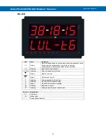
Страница 23: ...the programming buttons After power and signal connections have been completed and verified apply power to the scanner LED Status Indicators PD2 6080 LED State Indication 1 4 Steady Alarm condition b...

Страница 24: ...uding those without relays installed 1 4 Flashing Relay interlock switch open 1 4 M Flashing Relay in manual control mode 8 Steady Eighths of an inch 16 Steady Sixteenths of an inch F Flashing Communi...

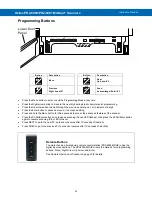
Страница 25: ...CAN Enter button again to resume scanning Play LED turns on Press NEXT to go to the next PV auto scan resumes after 10 seconds of inactivity Press PREV to go to the previous PV auto scan resumes after...

Страница 26: ...321 Byte Order Select little endian byte order 2143 Byte Order Select byte swapped big endian byte order Not available for Short integer Display Functions Messages Display Parameter Action Setting Des...

Страница 27: ...mmand setup Setup Enter Setup menu pV Process Variable Enter PV Setup menu PV 1 PV Select PV 1 16 tag Tag Tag units Units Units Display Functions Messages Display Parameter Action Setting Description...

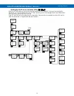
Страница 28: ...cted Relay turns on when Communications Break detected Off Off Relay goes to non alarm condition when break detected Relay turns off when Communications Break detected Display Functions Messages Displ...

Страница 29: ...e next digit and the Up arrow to increment the digit s value The digit being changed is displayed brighter than the rest Press and hold the Up arrow to auto increment the display value Press the Enter...

Страница 30: ...nect the RJ45 connector located to the left of the power terminal block Doing so will disable the on board digital I O and the RS 485 serial communications When using more than one scanner in a multi...

Страница 31: ...PV Number menu and press ENTER From there the user can scroll through all of the sixteen available PVs In order to enable a specific PV simply press ENTER to access the desired PV then scroll to ENABL...

Страница 32: ...er Poll Time and Response Timeout menus PV Number Enable disable PVs select slave ID function code register number data type byte order Poll Time Enter the time interval to poll the slave devices sele...

Страница 33: ...ossibility of communication errors and communication break conditions use a poll time of 5 seconds or more with slow baud rates e g 4800 bps or less 2 The response time for scanners set up for Snooper...

Страница 34: ...ber defaults to 30001 2 Default Data Type is Float 3 Default Slave ID for PV1 001 for PV2 002 for PV3 003 etc The Master ignores the decimal point setting for slave devices that specify a Short or Lon...

Страница 35: ...r setup The Setup menu is used to select 1 PV Setup a PV Tags b PV Units c Format Decimal point or Feet Inches d Decimal Point e Scale input data 2 Display assignment Intensity 3 Relay assignment and...

Страница 36: ...each enabled PV Once you have selected the desired PV you can select parameters for each These include tag units format display decimal point float decimal point resolution and scaling of the input da...

Страница 37: ...2 must be less than Input 3 etc known as monotonic values Press Enter to save the changes or Menu to exit without saving When the Linear function is selected for PV1 PV2 up to 32 points may be program...

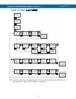
Страница 38: ...programmed to display any of the following Display Parameter Setting Description D pV Display PV Display PVs 1 16 D Ch C Display C Channel Display Math Channels C1 C4 PV unit Display PV Units Display...

Страница 39: ...canners Instruction Manual 39 Display Line 1 Menu Line 1 dsplay Note For Tag PVn and Tag PVn U the default settings for PVs are 1 3 5 7 followed by two underscores which represent empty PVs These all...

Страница 40: ...canners Instruction Manual 40 Display Line 2 Menu Line 2 dsplay Note For Tag PVn and Tag PVn U the default settings for PVs are 2 4 6 8 followed by two underscores which represent empty PVs These all...

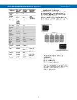
Страница 41: ...e position 3 Press and hold up arrow to auto scroll the characters in the display Application Example 1 In this application we have a system consisting of 4 multivariable tank level gauges connected t...

Страница 42: ...Average Temperature Data Type Long integer Binary Signed Long Byte Order 1234 1234 PV7 Slave ID 3 3 Function Code 04 04 Parameter PD2 6080 Master PD2 6080 Snooper Description Comment Register PV7 300...

Страница 43: ...face Display 1 000000 000000 Input 2 999999 999999 0 001 inch resolution Display 2 83 333 83 333 Feet Application Example 2 In this application we have a system consisting of 4 multivariable tank leve...

Страница 44: ...PVs 2 to 16 PVs 2 Act 1 Relay action a Automatic reset only non latching b Automatic manual reset at any time non latching c Latching manual reset only d Latching with Clear manual reset only after a...

Страница 45: ...elow the set point Note Changes are not saved until the reset point has been accepted Setting Fail Safe Operation failsf In fail safe mode of operation the relay coil is energized when the process var...

Страница 46: ...condition 3 Ignore Processed as a low signal condition Note Select no Action Time Delay Operation The following graphs show the operation of the time delay function When the signal crosses the set po...

Страница 47: ...must go below the set point and then go above it Low Alarm Operation Set Reset For Manual reset mode ACK can be pressed anytime to turn off relay For relay to turn back on signal must go above set poi...

Страница 48: ...off or on based on their operating mode and their set and reset points without regard to their prior state This is similar to the auto initialization on power up Below is a diagram showing three exam...

Страница 49: ...thout relays installed and provide status indication for the following LED Status 1 Alarm 1 2 Alarm 2 3 Alarm 3 4 Alarm 4 The scanner is supplied with four alarm points that include front panel LEDs t...

Страница 50: ...up for manual reset at any time Acknowledging the alarm even if the alarm condition is still present resets the relay and turns off the LED Manual reset any time Condition LED Relay Normal Off Off Al...

Страница 51: ...e programmed so that the first pump on is the first pump off Application 1 Pump Alternation Using Relays 1 2 Set and Reset Point Programming Relay Set Point Reset Point Function 1 30 000 10 000 Contro...

Страница 52: ...al inputs are assigned to the same relay then the corresponding logic is AND i e both switches must be closed to trip the relay If the digital inputs are assigned to the Interlock Function then they c...

Страница 53: ...age is being displayed and enter the correct password to gain access to the menu After exiting the programming mode the scanner returns to its password protected condition Disabling Password Protectio...

Страница 54: ...ect Automatic Scan Mode time Scan Time Select Scanning Time nman Manual Select Manual Scan Mode Alarnm Alarm Select Go or Stop Alarm go Go Select Alarm Go Stop Stop Select Alarm Stop Contrl Manual Con...

Страница 55: ...plied to other math channels e g C3 C1 C2 sunm Sum Math2 Function Sum dif Difference Math2 Function Difference Advanced Features Menu Display Messages Display Parameter Action Setting difabs Absolute...

Страница 56: ...mp High Signal Volt Volts Enter Volts V CAL Voltage Calibration Enter Voltage Calibration V Lo Voltage Low Signal Enter Voltage Low Signal V Hi Voltage High Signal Enter Voltage High Signal error Erro...

Страница 57: ...ontrl The Manual Control menu is used to control the 4 20 mA analog output and the relays manually ignoring the input Each relay and analog output can be programmed independently for manual control Se...

Страница 58: ...mmed to filter small input changes but allow larger input changes to be displayed immediately by setting the bypass value accordingly If the input signal goes beyond the bypass value it will be displa...

Страница 59: ...es a display that is linear with respect to the input data e g 0 000 0 000 10 000 10 000 and then 5 000 5 000 Linear Function Menu Linear Scanners are set up at the factory for linear function with 2...

Страница 60: ...um flow Programmable Exponent Function Menu prog e The programmable exponent function is used to calculate open channel flow measured with a level transmitter in weirs and flumes The flow rate is prop...

Страница 61: ...the volume in any engineering unit without the need to re enter the dimensions again Changing the Volume from Gallons to Liters In the graphic entering the 48 for the diameter and 120 for the length...

Страница 62: ...iFAbS Average PV1 PV2 2 P F AVG Multiplication PV1 PV2 P F Nmulti Division PV1 PV2 P F diVide Max PV Max value of all selected PVs Hi pV Min PV Min value of all selected PVs Lo pV Draw PV1 PV2 1 F drA...

Страница 63: ...digit represents one PV in hexadecimal format except PV16 G 3 PV1 PV9 1 9 PV10 PV16 A G 4 No PV selected underscore symbol 5 Digit range 1 G then _ 6 If there is an empty digit the scanner will end th...

Страница 64: ...1 Modbus Scanners Instruction Manual 64 Sum Menu sunm Difference Menu dif Difference Absolute Menu difAbS Average Menu aVg Multiplication Menu nmulti Divide Menu diVide Only two PVs at a time will be...

Страница 65: ...V Draw Menu drauw Only two PVs at a time will be used for this function Weighted Average Menu uwAvg Only two PVs at a time will be used for this function Ratio Menu ratio Only two PVs at a time will b...

Страница 66: ...nge absolute maximum and minimum output and communications break values They can also be recalibrated To calibrate the analog outputs follow the graphic above The overrange and underrange values are t...

Страница 67: ...loop that includes a power supply internal or external 12 to 24 VDC and the mA input on the digital meter See Figure 22 4 20 mA Output Connections on page 21 for details 2 Turn on all devices Allow fo...

Страница 68: ...stored minimum display values for all channels Rst HL Reset the stored maximum minimum display values for all channels relay Directly access the relay menu Set 1 Directly access the set point menu fo...

Страница 69: ...to the USER menu selecting a function key or digital input pressing ENTER to take you to the next level then pressing the Up arrow until you arrive at the RESET menu Press ENTER to assign the RESET me...

Страница 70: ...t the values entered or press Menu to exit calibration without saving the changes Error Message Error An error message indicates that the calibration or scaling process was not successful After the er...

Страница 71: ...vices 3 Baud rate and parity of all devices on the bus 4 Scanner Id must be different from other devices Snooper mode not reading the PVs on the RS 485 bus Check 1 Increase Master s Transmit Delay e g...

Страница 72: ...ettings Reset Scanner to Factory Defaults When the parameters have been changed in a way that is difficult to determine what s happening it might be better to start the setup process from the factory...

Страница 73: ...V 1 5 V 0 10 V 10 V and displaying these signals in engineering units from 99999 to 999999 e g a 4 20 mA signal could be displayed as 50 000 to 50 000 The analog input channels must be mapped to PVs u...

Страница 74: ...annel C1 4 Sunm Sum Adder constant P Adder 0 000 Factor constant F Factor 1 000 Factory Defaults User Settings Parameter Display Default Setting Filter Filter Filter PV 1 Ch A 70 Filter PV 2 Ch B 70 B...

Страница 75: ...errange output O rang 21 000 mA Underrange output u rang 3 000 mA Communications break output break 1 000 mA Maximum output nmAx 23 000 mA Minimum output nmin 1 000 mA F1 function key F1 Previous PV F...

Страница 76: ...www predig com LIM2 6080_D SFT088 Ver 2 020 up 08 21 Contact Precision Digital Technical Support Call 800 610 5239 or 508 655 7300 Fax 508 655 8990 Email support predig com Sales Support Call 800 343...

Отзывы: