


Helios PD2-6080/PD2-6081 Modbus
®
Scanners
Instruction Manual
17
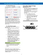
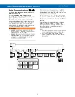
ScanView Monitoring
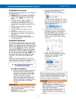
Once the scanner has been configured, the user
chooses Monitor from the top menu bar. The Monitor
window will appear; the enabled PVs and all
associated values will take a few seconds to display.
The PVs will display as configured - either in Decimal
or Feet & Inches format. Data Logging, Scanning, and
Alarm Status can all be viewed at the bottom of the
Monitor window.
ScanView Data Logging
ScanView software allows the user to log data and
generate reports.
1. Select Monitor - Stop Scan from the top
menu bar.
2. Select the Data Log drop-down menu from
the top menu bar. Parameters for Data
Logging are: Interval, Units, Log File Name,
and Start/Pause. For Interval the choices
are: 1-60, and for Unit choices for logging
data are: Seconds, Minutes, and Hours.
3. Save the Data Log File. It is recommended
to name the file using a unique name and
the date, such as:
"ScanView_1.00_Log_X_100813".
4. Select Monitor - Start Scan from the top
menu bar, then select Data Log - Start from
the top menu bar. The log file can be
retrieved at any time by following the path:
(C:) - Program Files (x86) - PDC -
ScanView 1.00 - Data Log.
•
Once Data Logging has begun, the Configure,
Customize, and Connection screens cannot be
accessed until the user has paused Data
Logging.
Data Log files are saved in the Data Log folder as
".CSV" files. To view Data Log files, the user must first
pause both Scanning and Data Logging. Data
Logging & Scan Status can be seen at the bottom of
the Monitor window.
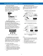
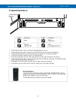
Transmitter Supply Voltage
Selection (P+, P-)
All scanners, including models equipped with the
12-24 VDC power option, are shipped from the
factory configured to provide 24 VDC power for
the transmitter or sensor.
If the transmitter requires 5 or 10 VDC excitation,
the switch labeled P+/P- must be configured
accordingly.
To access the voltage selection switch:
1. Turn off the power to the meter.
2. Unscrew and open the lower door panel.
3. Locate the P+/P- switch located in the
center of the connections board (see
diagram below).
4. Flip this switch into the appropriate
position for the required transmitter
excitation.
Figure 8. Transmitter Supply Voltage Selection
P+/P-
24V 10V 5V
MENU RIGHT UP ACK
MENU
PREV
F1
NEXT
F2
SCAN
F3


