


Helios PD2-6080/PD2-6081 Modbus
®
Scanners
Instruction Manual
73
Scanner Operation
The PD2-6080/1 scanner is capable of operating as a
Modbus Master, Slave or Snooper. As a Slave, the
PD2-6080/1 requires connection to a Master device:
PLC, DCS, etc. As a Master, the PD2-6080/1
interfaces up to sixteen slave devices and can
alternately display their Process Variables. As a
Snooper it can be connected anywhere in the RS-485
bus to read any of the variables being requested by
the Master device.
Four math channels (C1-C4) are available to perform
operations on any PV or math channel, with adder
and factor constants, and display the results.
Engineering units or tags may be displayed with all
PVs or math channels. Another level of Math
functions can be performed on the resultant math
channel Math2. For example, the operator can use
the Math2 Channel to calculate the Sum of all other
Math Channels, which may have each performed a
different Math function.
The dual-line display can be customized by the user.
Typically, the upper display is used to display the PV,
while the lower display is used to display the tag for
each PV.
Additionally, the scanner can be set up to display any
input or math channel on the upper display and
alternate between tag & units on the lower display.
The relays and analog output can be programmed to
operate based on any PV or math channel.
The scanner is capable of accepting two analog input
channels (A and B) of either current (0-20 mA,
4-20 mA) or voltage signals (0-5 V, 1-5 V, 0-10 V,
10 V) and displaying these signals in engineering
units from -99999 to 999999 (
e.g.
a 4-20 mA signal
could be displayed as -50.000 to 50.000). The analog
input channels must be mapped to PVs using the
Slave IDs 256-259.
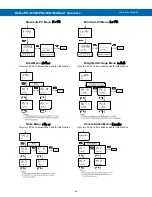
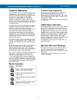
Button Operation
Button
Symbol
Description
Press to enter, exit Programming
Mode, or exit max/min readings
Press to move to the previous PV or
math channel
Press to move to the next PV or math
channel
Press once to pause scanning, press
again to resume scanning
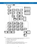
Function Keys Operation
During operation, the programmable function keys
operate according to the way they have been
programmed in the
Advanced Features
– User
menu.
Programmable Function Keys User Menu
The table above shows the factory default settings for
F1, F2, and F3.
Digital Inputs Operation
Five (5) digital inputs, F4, DI-1 to DI-4, come standard
on the meter. These digital inputs are programmed
identically to function keys F1, F2, and F3. The inputs
are triggered with a contact closure to +5 in the case
of digital inputs 1-4 or with an active high signal, see
is triggered with a contact closure to COM or with an
active low signal. During operation, digital inputs
operate according to the way they are programmed in
the Advanced Features
– User menu.. See
Programmable Function Keys User Menu
) on
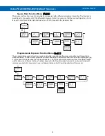
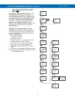
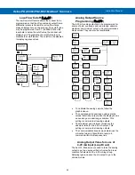
Maximum/Minimum Readings
The max & min readings (peak & valley) reached by
the PVs or math channels can be displayed by
assigning the display to max/min through the
Display
Setup
menu.
A digital input should be programmed to reset the
max & min readings.
MENU
MENU
RIGHT
PREV
F1
UP
NEXT
F2
ACK
SCAN
F3


