


Helios PD2-6080/PD2-6081 Modbus
®
Scanners
Instruction Manual
22
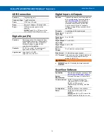
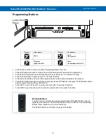
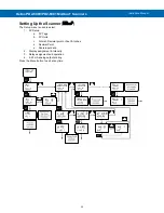
Remote Operation of Scanner
The scanner can be operated via the programming
buttons or a PDA2364-MRUE remote control station
using the digital inputs and outputs connections as
illustrated in
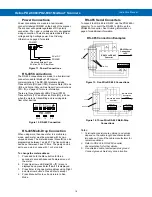
Figure 24. Meter to PDA2364-MRUE
Figure 24. Meter to PDA2364-MRUE Control
Station Connection
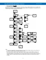
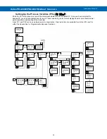
Interlock Relay Feature
As the name implies, the interlock relay feature
reassigns one, or more, alarm/control relays for use
as interlock relay(s). Interlock contact(s) are wired to
digital input(s) and trigger the interlock relay. This
feature is enabled by configuring the relay, and the
corresponding digital input(s). See
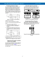
Interlock Relay (Force On) Feature
In the example below, an Interlock Contact switch is
connected to a digital input, which will be used to
force on (energize) the Interlock Relay. The Interlock
Relay and the Control Relay are connected in series
with the load.
•
When the Interlock Contact is closed (safe), the
Interlock Relay energizes, allowing power to flow
to the Control Relay; the corresponding front
panel LED is on.
•
When the Interlock Contact is open, the
corresponding front panel LED flashes (locked
out), the Interlock Relay is de-energized,
preventing power from flowing to the Control
Relay and the load.
Figure 25. Interlock Connections
Analog Input Signal Connections
Analog input signal connections are made to a nine-
terminal connector labeled SIGNAL. The COM
(common) terminals are the return for the 4-20 mA
and the
10 V input signals. The two COM terminals
connect to the same common return and are not
isolated.
Current and Voltage Connections
The following figures show examples of current and
voltage connections. There are no switches or jumpers
to set up for current and voltage inputs. Setup and
programming is performed through the programming
buttons or using ScanView software.
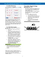
Figure 26. Transmitters Powered by Internal
Supply
Figure 27. Transmitter Powered by Ext. Supply or
Self-Powered
The current input is protected against current
overload by a resettable fuse. The display may or
may not show a fault condition depending on the
nature of the overload.
The fuse limits the current to a safe level when it
detects a fault condition, and automatically resets
itself when the fault condition is removed.
Figure 28. Voltage Input Connections
The scanner is capable of accepting any voltage from
-10 VDC to +10 VDC.