- 54 -
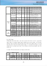
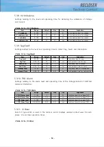
5.3.8. V/I Unbalance
Settings relating to the level and operating time for detecting the unbalance of Voltage
and Current.
<Table 5-13> V/I Unbalance
Item
Range
Default
Step
Unit
Explanation
V unbalance
0~100
0
1
%
Set unbalance level for voltage
V unbalance time
0.1~60
0.1
0.1
sec
Set unbalance time for voltage
I unbalance
0~100
0
1
%
Set unbalance level for current
I unbalance time
0.1~60
0.1
0.1
sec
Set unbalance time for current
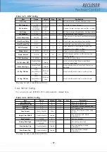
5.3.9. Sag/Swell
Settings related to the level and operating time to detect Sag, Swell, and Interruption.
<Table 5-14> Sag/Swell
Item
Range
Default
Step
Unit
Explanation
Sag Level
50~99
90
1
%
Set pickup level for sag
Sag Time
0.02~10
1.0
0.01
sec
Set operation time for sag
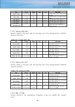
Swell Level
101~150
120
1
%
Set pickup level for swell
Swell Time
0.02~10
1.0
0.01
sec
Set operation time for swell
Interrupt Level
10~50
10
1
%
Set pickup level for interruption
Interrupt Time
0.02~10
1.0
0.01
sec
Set operation time for interruption
5.3.10. THD Alarm
Settings relating to the alarm level and operating time of the Voltage/Current’s THD(Total
Harmonic Distortion).
<Table 5-15> THD Alarm
Item
Range
Default
Step
Unit
Explanation
V THD Alarm Level
1~100
3
1
%
Set alarm level for voltage THD
V THD Alarm Time
0.02~60.00
0.02
0.01
sec
Set alarm time for voltage THD
I THD Alarm Level
1~100
3
1
%
Set alarm level for current THD
I THD Alarm Time
0.02~60.00
0.02
0.01
sec
Set alarm time for current THD
5.3.11. VI Wear
Select VI type which is used in the recloser, and it displays residual contact wear for each
phase’ VI and total operation times.
<Table 5-16> VI Wear
Содержание RECLOSER
Страница 1: ...User Manual Document Version 1 5 Feb 28 2019 http powersys kr http www powersys kr...
Страница 14: ...8 3 5 Mechanical Performance and Size Weight 3 5 kg FRONT VIEW Figure 3 1 Front View...
Страница 15: ...9 SIDE VIEW 343 00 310 00 91 00 Figure 3 2 Side View...
Страница 16: ...10 TOP VIEW 84 0 260 0 225 0 1 0 0t Figure 3 3 Top View...
Страница 17: ...11 REAR VIEW 180 0 120 0 Figure 3 4 Rear View...
Страница 22: ...16 Controller PCB 215 00 103 90 121 10 112 50 112 50 235 00 205 00 Figure 3 8 Controller PCB...
Страница 69: ...63...
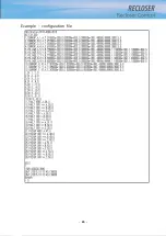
Страница 71: ...65 Example configuration file...
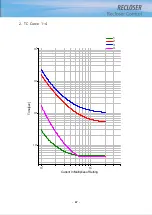
Страница 73: ...67 2 TC Curve 1 4 100 101 10 1 100 101 102 Time sec Current In Multiplies of Setting 1 2 3 4...
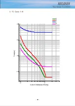
Страница 74: ...68 3 TC Curve 5 8 100 101 10 1 100 101 102 Time sec Current In Multiplies of Setting 5 6 7 8...
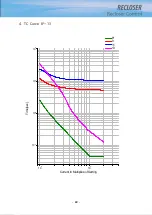
Страница 75: ...69 4 TC Curve 8 13 100 101 10 1 100 101 102 Time sec Current In Multiplies of Setting 8 9 11 13...
Страница 76: ...70 5 TC Curve 14 18 100 101 10 1 100 101 102 Time sec Current In Multiplies of Setting 14 15 16 18...
Страница 77: ...71 6 TC Curve A D 100 101 10 1 100 101 102 Time sec Current In Multiplies of Setting A B C D...
Страница 78: ...72 7 TC Curve E M 100 101 10 1 100 101 102 Time sec Current In Multiplies of Setting E K L M...
Страница 79: ...73 8 TC Curve N T 100 101 10 1 100 101 102 Time sec Current In Multiplies of Setting N P R T...
Страница 80: ...74 9 TC Curve V Z 100 101 10 1 100 101 102 Time sec Current In Multiplies of Setting V W Y Z...
Страница 84: ...78 13 TC Curve ES NI VI 100 101 10 1 100 101 102 ES NI ES VI Current In Multiplies of Setting Time sec...
Страница 85: ...79 14 TC Curve KEPCO N1 N4 100 101 10 1 100 101 102 Time sec Current In Multiplies of Setting N1 N2 N3 N4...
Страница 86: ...80 15 TC Curve DEF 1S 10S 100 101 10 1 100 101 DEF 1S DEF 10S Current In Multiplies of Setting Time sec...

