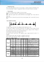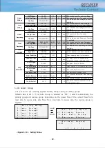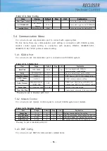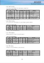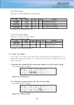
- 50 -
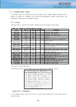
5.3. Configuration Menu
It provides menus for analog current and voltage input related setting, Debounce Time
setting to prevent DI chattering, DO output pulse adjustment related setting, Event Log
information setting and clear related setting.
5.3.1. Analog
Analog voltage / current input related setting items and ranges are like below.
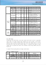
<Table 5-6> Setting for Analog voltage / current
The order to set is like below.
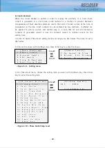
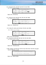
1) Choose the menu with Up/Down Key. Press Enter Key to enter the menu.
[
C o n f
i
g
M e n u ]
-> 1 .
A n a l
o g
2 .
D I
D e b o u n c e
T i
m e
3 .
D O
P u l
s e
T i
m e
4 .
B a c k u p
S e t / C l
e a r
5 .
A n a l
o g
G a i
n
A d j
6 .
W a v e f
o r m
7 .
C h e c k
A u t o
B a t t
8 .
V / I
U n b a l
a n c e
9 .
S a g / S w e l
l
1 0 .
T H D
A l
a r m
<Figure 5-15> Config Menu
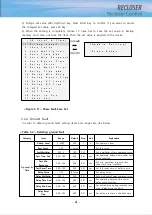
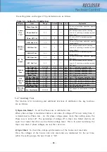
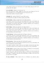
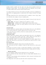
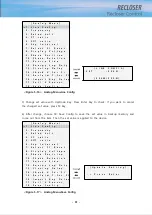
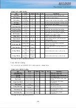
2) On Analog menu, choose the item you want with Up/Down Key. Press Enter Key to
enter the item.
Item
Range
Default
Step
Unit
Explanation
Line Config
3P4W/3P3W
3P4W
Distribution line’s connection
Frequency
50/60
60Hz
Distribution line’s frequency
Rated Voltage
3.8~21
13.2
0.01
kV
Distribution line’s rated voltage
CT ratio
100~2000
1000
1
CT ratio
NCT ratio
100~2000
1000
1
NCT ratio
Avg Interval
5-15
15
5
min
Average process time about demand value
Select FI Reset
Auto/Man
Man
Way to FI reset
Refer 5.2.2
Display voltage
L-N/L-L
L-N
Selection of line to phase voltage and line to line voltage
Phase Position
ABC/ACB/BCA/
BAC/CAB/CBA
ABC
Select phase position
Phase Rotation
ABC/ACB
ABC
Select whether phase rotation is ABC or ACB
Source Side
ABC/RST
ABC
Select which side will be power source between
ABC side and RST side
Energy Log Duty
Week/Month
Week
Set duty time for energy logging
Closing Delay
0~300
0
1
sec
Set delay time to close CB
Check V for FI
NO/YES
YES
Select whether to consider voltage when FI set
Reclaim T for FI
0~120
2
1
sec
Set reclaim time for FI
Import Key Delay
1~5
1
1
sec
Set import key delay
Fail V Sensor
0~120
10
1
sec
Set delay time for voltage sensor fail
I Cut Level
0~10
0.1
0.1
%
Set level for current cutting
V Cut Level
0~50
10
1
%
Set level for current cutting
Содержание RECLOSER
Страница 1: ...User Manual Document Version 1 5 Feb 28 2019 http powersys kr http www powersys kr...
Страница 14: ...8 3 5 Mechanical Performance and Size Weight 3 5 kg FRONT VIEW Figure 3 1 Front View...
Страница 15: ...9 SIDE VIEW 343 00 310 00 91 00 Figure 3 2 Side View...
Страница 16: ...10 TOP VIEW 84 0 260 0 225 0 1 0 0t Figure 3 3 Top View...
Страница 17: ...11 REAR VIEW 180 0 120 0 Figure 3 4 Rear View...
Страница 22: ...16 Controller PCB 215 00 103 90 121 10 112 50 112 50 235 00 205 00 Figure 3 8 Controller PCB...
Страница 69: ...63...
Страница 71: ...65 Example configuration file...
Страница 73: ...67 2 TC Curve 1 4 100 101 10 1 100 101 102 Time sec Current In Multiplies of Setting 1 2 3 4...
Страница 74: ...68 3 TC Curve 5 8 100 101 10 1 100 101 102 Time sec Current In Multiplies of Setting 5 6 7 8...
Страница 75: ...69 4 TC Curve 8 13 100 101 10 1 100 101 102 Time sec Current In Multiplies of Setting 8 9 11 13...
Страница 76: ...70 5 TC Curve 14 18 100 101 10 1 100 101 102 Time sec Current In Multiplies of Setting 14 15 16 18...
Страница 77: ...71 6 TC Curve A D 100 101 10 1 100 101 102 Time sec Current In Multiplies of Setting A B C D...
Страница 78: ...72 7 TC Curve E M 100 101 10 1 100 101 102 Time sec Current In Multiplies of Setting E K L M...
Страница 79: ...73 8 TC Curve N T 100 101 10 1 100 101 102 Time sec Current In Multiplies of Setting N P R T...
Страница 80: ...74 9 TC Curve V Z 100 101 10 1 100 101 102 Time sec Current In Multiplies of Setting V W Y Z...
Страница 84: ...78 13 TC Curve ES NI VI 100 101 10 1 100 101 102 ES NI ES VI Current In Multiplies of Setting Time sec...
Страница 85: ...79 14 TC Curve KEPCO N1 N4 100 101 10 1 100 101 102 Time sec Current In Multiplies of Setting N1 N2 N3 N4...
Страница 86: ...80 15 TC Curve DEF 1S 10S 100 101 10 1 100 101 DEF 1S DEF 10S Current In Multiplies of Setting Time sec...

