- 55 -
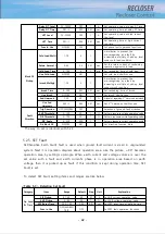
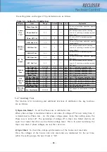
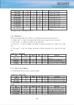
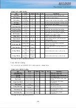
Item
Range
Default
Step
Unit
Explanation
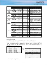
Max Op Count
1000~10000
2000
1
Set the type of the VI used in the
recloser
Alarm Level
0~100
45
1
%
Set alarm level for residual contact
wear
Duty Factor A
0~100
100
1
%
Set duty factor for A phase’s VI
Duty Factor B
0~100
100
1
%
Set duty factor for B phase’s VI
Duty Factor C
0~100
100
1
%
Set duty factor for C phase’s VI
Clear Wear Info
Delete save wear information in
backup memory
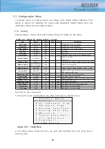
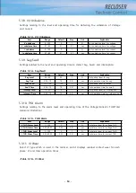
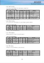
5.3.12. Analog High Alm
Settings relating to the alarm level and operating time of the Voltage/Current’s THD(Total
Harmonic Distortion).
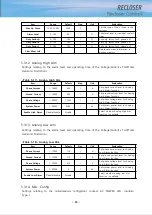
<Table 5-17> Analog High Alm
Item
Range
Default
Step
Unit
Explanation
Phase Current
1~16000
400
1
A
Set phase current level for Analog
High Alarm function
Ground Current
1~16000
400
1
A
Set ground current level for Analog
High Alarm function
Phase Voltage
1~38000
13200
1
V
Set phase voltage level for Analog
High Alarm function
System Power
1~54000
5280
1
kV
Set system power level for Analog
High Alarm function
Enable High Alarm
Disable/Enable
Disable
Select whether Analog High Alm
function is available
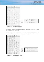
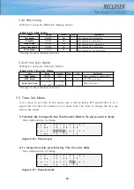
5.3.13. Analog Low Alm
Settings relating to the alarm level and operating time of the Voltage/Current’s THD(Total
Harmonic Distortion).
<Table 5-18> Analog Low Alm
Item
Range
Default
Step
Unit
Explanation
Phase Current
1~15999
110
1
A
Set phase current level for Analog
Low Alarm function
Ground Current
1~15999
110
1
A
Set ground current level for Analog
Low Alarm function
Phase Voltage
1~37999
510
1
V
Set phase voltage level for Analog
Low Alarm function
System Power
1~53999
0
1
kV
Set system power level for Analog
Low Alarm function
Enable Low Alarm
Disable/Enable
Disable
Select whether analog low alm
function is available
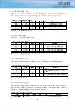
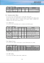
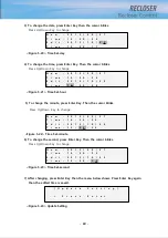
5.3.14. Misc. Config
Settings relating to the miscellaneous config(Door contact, AC POWER LED, Insulator
Type...).
Содержание RECLOSER
Страница 1: ...User Manual Document Version 1 5 Feb 28 2019 http powersys kr http www powersys kr...
Страница 14: ...8 3 5 Mechanical Performance and Size Weight 3 5 kg FRONT VIEW Figure 3 1 Front View...
Страница 15: ...9 SIDE VIEW 343 00 310 00 91 00 Figure 3 2 Side View...
Страница 16: ...10 TOP VIEW 84 0 260 0 225 0 1 0 0t Figure 3 3 Top View...
Страница 17: ...11 REAR VIEW 180 0 120 0 Figure 3 4 Rear View...
Страница 22: ...16 Controller PCB 215 00 103 90 121 10 112 50 112 50 235 00 205 00 Figure 3 8 Controller PCB...
Страница 69: ...63...
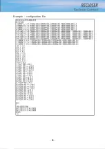
Страница 71: ...65 Example configuration file...
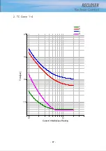
Страница 73: ...67 2 TC Curve 1 4 100 101 10 1 100 101 102 Time sec Current In Multiplies of Setting 1 2 3 4...
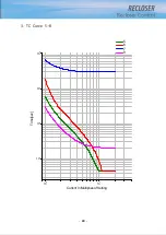
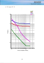
Страница 74: ...68 3 TC Curve 5 8 100 101 10 1 100 101 102 Time sec Current In Multiplies of Setting 5 6 7 8...
Страница 75: ...69 4 TC Curve 8 13 100 101 10 1 100 101 102 Time sec Current In Multiplies of Setting 8 9 11 13...
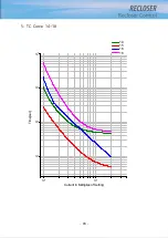
Страница 76: ...70 5 TC Curve 14 18 100 101 10 1 100 101 102 Time sec Current In Multiplies of Setting 14 15 16 18...
Страница 77: ...71 6 TC Curve A D 100 101 10 1 100 101 102 Time sec Current In Multiplies of Setting A B C D...
Страница 78: ...72 7 TC Curve E M 100 101 10 1 100 101 102 Time sec Current In Multiplies of Setting E K L M...
Страница 79: ...73 8 TC Curve N T 100 101 10 1 100 101 102 Time sec Current In Multiplies of Setting N P R T...
Страница 80: ...74 9 TC Curve V Z 100 101 10 1 100 101 102 Time sec Current In Multiplies of Setting V W Y Z...
Страница 84: ...78 13 TC Curve ES NI VI 100 101 10 1 100 101 102 ES NI ES VI Current In Multiplies of Setting Time sec...
Страница 85: ...79 14 TC Curve KEPCO N1 N4 100 101 10 1 100 101 102 Time sec Current In Multiplies of Setting N1 N2 N3 N4...
Страница 86: ...80 15 TC Curve DEF 1S 10S 100 101 10 1 100 101 DEF 1S DEF 10S Current In Multiplies of Setting Time sec...

