- 33 -
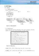
4.3. Order of Installation Test Operation
① Check if the connection is right. Turn On the control power.
② Check CT/PT rate on System Config. Menu. If necessary, adjust it following CT/PT rate control.
③ Check connection system on System Config. Menu. If necessary, adjust it.
④ Check & Control Alarm contact’s setting state on DO Config. Menu. If necessary, adjust it.
⑤ On Relay setting menu, check if Relays are correctly setting. If necessary, adjust it.
⑥ After all adjustments, EPIC-R300 works properly.
⑦ If RUN LED on front panel blinks regularly and SYS-FAIL LED is turned off, which
means it works properly.
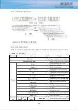
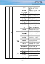
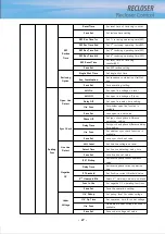
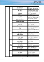
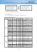
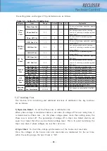
PSTN
Config
PSTN Modem
Select PSTN mode type, PPP, dialup
or SMS
Auto Hangup Time
Set Auto hangup time
Dial Timeout
Set dial timeout
Attempt Delay
Set dial attempt delay time
Max Attempts
Set dial max attempt
Save PSTN Set
Save PSTN related setting
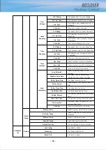
PPP
Config
Our IP Addr
Set our IP address
Their IP Addr
Set their IP address
DNS1 IP Addr
Set DNS1 IP address
DNS2 IP Addr
Set DNS2 IP address
Save PPP Set
Save PPP related setting
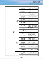
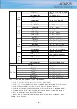
SMS
Config
Trip Enable
Set sending trip information
FI Enable
Set sending FI information
Open Enable
Set sending open information
Door Open Enable
Set sending door information
AC fail Enable
Set sending AC fail information
Save SMS Set
Save SMS related setting
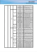
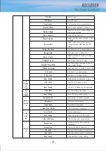
Time
sync
option
SNTP sync Enable
Select whether to enable SNTP
SNTP sync Period
Set SNTP cycle duty
Select Time Zone
Select time zone
Save TimeSync Set
Save TimeSync related setting
Time Set
Time setting
Event View
Fault Event
Fault event
Op Event
Display Operation event
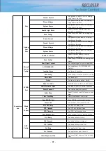
Demand I
Display Demand current
Demand P
Display Demand power
Max Demand I
Display Max demand current
Max Demand P
Display Max demand Power
Содержание RECLOSER
Страница 1: ...User Manual Document Version 1 5 Feb 28 2019 http powersys kr http www powersys kr...
Страница 14: ...8 3 5 Mechanical Performance and Size Weight 3 5 kg FRONT VIEW Figure 3 1 Front View...
Страница 15: ...9 SIDE VIEW 343 00 310 00 91 00 Figure 3 2 Side View...
Страница 16: ...10 TOP VIEW 84 0 260 0 225 0 1 0 0t Figure 3 3 Top View...
Страница 17: ...11 REAR VIEW 180 0 120 0 Figure 3 4 Rear View...
Страница 22: ...16 Controller PCB 215 00 103 90 121 10 112 50 112 50 235 00 205 00 Figure 3 8 Controller PCB...
Страница 69: ...63...
Страница 71: ...65 Example configuration file...
Страница 73: ...67 2 TC Curve 1 4 100 101 10 1 100 101 102 Time sec Current In Multiplies of Setting 1 2 3 4...
Страница 74: ...68 3 TC Curve 5 8 100 101 10 1 100 101 102 Time sec Current In Multiplies of Setting 5 6 7 8...
Страница 75: ...69 4 TC Curve 8 13 100 101 10 1 100 101 102 Time sec Current In Multiplies of Setting 8 9 11 13...
Страница 76: ...70 5 TC Curve 14 18 100 101 10 1 100 101 102 Time sec Current In Multiplies of Setting 14 15 16 18...
Страница 77: ...71 6 TC Curve A D 100 101 10 1 100 101 102 Time sec Current In Multiplies of Setting A B C D...
Страница 78: ...72 7 TC Curve E M 100 101 10 1 100 101 102 Time sec Current In Multiplies of Setting E K L M...
Страница 79: ...73 8 TC Curve N T 100 101 10 1 100 101 102 Time sec Current In Multiplies of Setting N P R T...
Страница 80: ...74 9 TC Curve V Z 100 101 10 1 100 101 102 Time sec Current In Multiplies of Setting V W Y Z...
Страница 84: ...78 13 TC Curve ES NI VI 100 101 10 1 100 101 102 ES NI ES VI Current In Multiplies of Setting Time sec...
Страница 85: ...79 14 TC Curve KEPCO N1 N4 100 101 10 1 100 101 102 Time sec Current In Multiplies of Setting N1 N2 N3 N4...
Страница 86: ...80 15 TC Curve DEF 1S 10S 100 101 10 1 100 101 DEF 1S DEF 10S Current In Multiplies of Setting Time sec...

