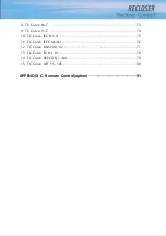
CONTENTS
1. Safety Information
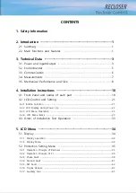
2. Introduction ························································································ 1
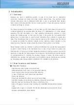
2.1. Summary ··········································································································· 1
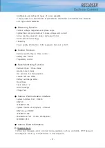
2.2. Main functions and features ······································································· 1
3. Technical Data ··················································································· 3
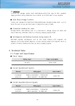
3.1. Power and Input/Output ·············································································· 3
3.2. Environmental ·································································································· 5
3.3. Communication ······························································································· 6
3.4. Measurements ································································································· 7
3.5. Mechanical Performance and Size ····························································· 8
4. Installation Instructions ···································································· 18
4.1. Front Panel and names of each part ······················································· 18
4.2. LCD Control and Setting ············································································· 21
4.2.1 Button Function ····················································································································· 21
4.2.2 LCD Display during Power Up ·························································································· 22
4.2.3 LCD Menu Operation ·········································································································· 23
4.2.4. LCD Menu Items ·················································································································· 23
4.3. Order of Installation Test Operation ························································ 33
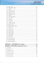
5. LCD Menu ··························································································· 34
5.1. Display ··············································································································· 34
5.1.1. Display operation ················································································································· 34
5.1.2. Display Menu ························································································································ 34
5.2. Protection Setting Menu ·············································································· 35
5.2.1. Operation Principle of Recloser ······················································································· 35
5.2.2. Operation Principle of FI ··································································································· 36
5.2.3. Phase Fault ···························································································································· 38
5.2.4. Ground Fault ························································································································· 41
5.2.5. SEF Fault ································································································································· 42
5.2.6. Trip & Reclose ······················································································································ 43
5.2.7. Auxiliary Func ························································································································ 45
Содержание RECLOSER
Страница 1: ...User Manual Document Version 1 5 Feb 28 2019 http powersys kr http www powersys kr...
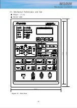
Страница 14: ...8 3 5 Mechanical Performance and Size Weight 3 5 kg FRONT VIEW Figure 3 1 Front View...
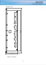
Страница 15: ...9 SIDE VIEW 343 00 310 00 91 00 Figure 3 2 Side View...
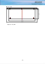
Страница 16: ...10 TOP VIEW 84 0 260 0 225 0 1 0 0t Figure 3 3 Top View...
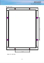
Страница 17: ...11 REAR VIEW 180 0 120 0 Figure 3 4 Rear View...
Страница 22: ...16 Controller PCB 215 00 103 90 121 10 112 50 112 50 235 00 205 00 Figure 3 8 Controller PCB...
Страница 69: ...63...
Страница 71: ...65 Example configuration file...
Страница 73: ...67 2 TC Curve 1 4 100 101 10 1 100 101 102 Time sec Current In Multiplies of Setting 1 2 3 4...
Страница 74: ...68 3 TC Curve 5 8 100 101 10 1 100 101 102 Time sec Current In Multiplies of Setting 5 6 7 8...
Страница 75: ...69 4 TC Curve 8 13 100 101 10 1 100 101 102 Time sec Current In Multiplies of Setting 8 9 11 13...
Страница 76: ...70 5 TC Curve 14 18 100 101 10 1 100 101 102 Time sec Current In Multiplies of Setting 14 15 16 18...
Страница 77: ...71 6 TC Curve A D 100 101 10 1 100 101 102 Time sec Current In Multiplies of Setting A B C D...
Страница 78: ...72 7 TC Curve E M 100 101 10 1 100 101 102 Time sec Current In Multiplies of Setting E K L M...
Страница 79: ...73 8 TC Curve N T 100 101 10 1 100 101 102 Time sec Current In Multiplies of Setting N P R T...
Страница 80: ...74 9 TC Curve V Z 100 101 10 1 100 101 102 Time sec Current In Multiplies of Setting V W Y Z...
Страница 84: ...78 13 TC Curve ES NI VI 100 101 10 1 100 101 102 ES NI ES VI Current In Multiplies of Setting Time sec...
Страница 85: ...79 14 TC Curve KEPCO N1 N4 100 101 10 1 100 101 102 Time sec Current In Multiplies of Setting N1 N2 N3 N4...
Страница 86: ...80 15 TC Curve DEF 1S 10S 100 101 10 1 100 101 DEF 1S DEF 10S Current In Multiplies of Setting Time sec...

