background image

www.wavetronix.com  

801.734.7200

QUICK START GUIDE

Click 304 USB to Serial

2

  Wire power and communication

If you are using a Click 200 surge protector, power and communication are provided to the device through 

the T-bus (see the Click 200 Quick-reference Guide). If you don’t have a Click 200 surge protector, use the 

following steps to wire power and communication into the device:

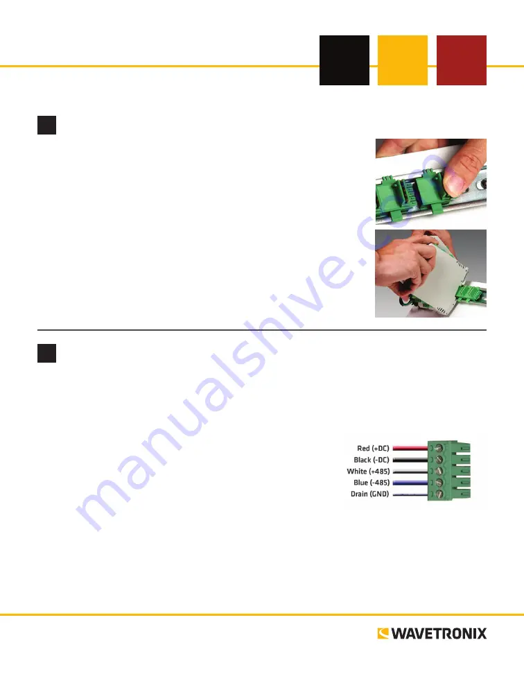
Plug a T-bus 5-screw terminal block into the first T-bus connector.

Wire DC power (10–30 V) from the power supply into the first 

screw terminal on the 5-screw terminal block; wire -DC into the 

second screw terminal.

C485, -485 and GND to either the remaining three 

screw terminals on the 5-screw terminal block or to the screw 

terminals in the pluggable screw terminal block on the top of the 

device (see labels for correct wiring).

The Click 304 has a few other communication ports.


˽

DB-9 connector –

 Connect a straight-through cable for RS-232 communication


˽

RJ-11 jack –

 Connect a jumper cable for RS-485 communication

1

  Mount the device

Each device mounts over a T-bus for power and communication:

If the device was shipped with the T-bus connector attached, remove the 

connector from the module.

Snap the connector onto the DIN rail by positioning it over the rail with 

the male connector pointing to the right. Hook one arm over the edge of 

the DIN rail and press down on the other arm until it snaps into place.

Connect the T-bus connector to the rest of the T-bus by sliding them 

together until you hear them snap into place.

Mount the device onto the DIN rail: position it properly over the T-bus 

connector, hook the lip over the lower edge of the DIN rail, and use a 

rocking motion to snap the module into place.

Содержание Click 304

Страница 1: ...minal block on the top of the device see labels for correct wiring The Click 304 has a few other communication ports DB 9 connector Connect a straight through cable for RS 232 communication RJ 11 jack Connect a jumper cable for RS 485 communication 1 Mount the device Each device mounts over a T bus for power and communication 1 If the device was shipped with the T bus connector attached remove the...

Страница 2: ...linking to reset to factory defaults Note On certain devices the yellow LED may replace the green LED in the autobaud process that is the yellow LED selects the autobaud process is on during the autobaud process etc LED activity indicating functions Red Shows device has power Yellow Shows device is transmitting data Green Shows device is receiving data 4 Install Click Supervisor Note Your device i...

Страница 3: ...ck on the main screen You will see the following two driv ers SmartSensor This driver is used if you plan on connecting from a TOC to your device to your sensor You can use this driver to view and change certain basic functional and informational settings such as baud rate de vice description and device location Expert This driver exposes all device settings and should be used only when you are in...

Страница 4: ...emarks or registered trademarks of their respective holders Product specifications are subject to change without notice This material is provided for informational purposes only Wavetronix assumes no liability related to its use 9 Verify the connection To verify the serial connection on the Click 304 1 Connect a straight through cable between the DB 9 connector on the front of the Click 304 and yo...

Отзывы: