background image

Admiral 38C Scrubber PB# 4100055UM  Rev.* 08/10                                                 

PowerBoss, Inc. Copyright 2010

Page  39

Operation

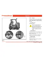
3.2.4 

Operating elements on the 

vehicle

(1)  Waste water filter

(2)  Solution tank filling neck

(3)  Lid lock

(4)  Cover, solution tank

(5)  Cover, recovery tank

(6)  Waste water draining hose

(7)  Solution draining hose

(8)  Left-hand rear door

(9)  Rear panel frame lock

(10) Rear panel frame

(11) Right-hand rear door

Fig 19   

Содержание Admiral 38C

Страница 1: ...Admiral 38C Scrubber PB 4100055UM Rev 08 10 PowerBoss Inc Copyright 2010 Page 1 User Manual Admiral 38C Cylindrical Sweeper Scrubber PowerBoss Inc A Member Of The Hako Group PB 4100055UM Rev 08 10 ...

Страница 2: ...he vehicle for future reference or subsequent owners We are certain that the excellent qualities of the vehicle will justify the faith you have shown in us through your purchase Please read the Chapter Safety Informa tion prior to starting the vehicle to ensure it is operated and used safely Your safety and that of others basically lies in your ability to control and operate the vehicle Therefore ...

Страница 3: ... concerning service and maintenance Maintenance work must be performed at authorized PowerBoss service centers and confirmed in the Maintenance Report which serves as a warranty logbook The following are excluded from the terms of warranty wear and tear through over use defective fuses improper handling or unauthorized modifications Claims under the terms of warranty are annulled when damage occur...

Страница 4: ...rbines suction 24 3 1 4 Solution tank 24 3 1 5 Recovery tank 24 3 1 6 Traction drive 25 3 1 7 Brakes 25 3 1 8 Batteries and charger 25 3 1 9 Options 26 3 2 Operating and indicator elements 29 3 2 1 Operating elements in the driver s cab 29 3 2 2 Left hand operating panel 32 3 2 3 Right hand operating panel 36 3 2 4 Operating elements on the vehicle 39 3 3 Operation 43 3 3 1 Switching the vehicle o...

Страница 5: ...4 Cleaning the air intake filter 74 5 6 5 Cleaning the openings to the solution tank 74 5 7 Rotary brush head 75 5 7 1 Emptying and cleaning the waste container 76 5 7 2 Changing the rotary brushes 77 5 7 3 Cleaning the contact surfaces 78 5 7 4 Adjusting the locking lever for the brush holder 78 5 7 5 Installing new rubber deflector strips 79 5 7 6 Adjusting the rotary brush head 79 5 7 7 Directi...

Страница 6: ...oughout the operating manual Symbol Hazardous for Definition Danger persons or property Safety information to prevent the development of hazardous situations resulting from ignoring or failing to follow instruc tions or prescribed work procedures Note the equipment Important information on handling the equipment in order to maintain its operability Ecological hazard the environment Risk to the env...

Страница 7: ...s a result should kept in a safe place on the vehicle If the equipment is sold or rented out these documents should be transferred to the new owner operator The transfer should be confirmed The warning labels attached to the equipment provide important informa tion concerning safe operation Labels which are illegible or missing must be replaced Original spare parts must be used to ensure safety If...

Страница 8: ...vided by the cleaning agent manufacturer It is forbidden to use the vehicle in potentially explosive atmospheres The machine is not suitable for clearing up health hazardous inflammable or explosive fluids dust or substances Ride on equipment may only be set into motion from the seat seat contact switch The seat contact switch must never be bypassed or the function immobilized in any way e g by pl...

Страница 9: ...It is not permitted to clean the vehicle with a pressure washer or steam blaster Clean the recovery tank regularly to protect it from the accumulation of dirt viruses bacteria etc It is not permitted to use aggressive and corrosive cleaning agents Allow the vehicle to dry after being cleaned e g over the weekend The vehicle must be checked by a recognized technical expert in respect of operational...

Страница 10: ...ttery plug be fore starting any work on the electrical installations Only use original fuses with the pre scribed amperage In the case of defects in the electrical installation switch the vehicle off im mediately and clear the fault Work on the electrical equipment may only be carried out by electricians who have received the necessary training and in accordance with the electrical engineering reg...

Страница 11: ... and the envi ronment Always observe legal regulations and local directives when disposing of cleaning agents Used batteries with the recycling symbol contain reusable commodities The heavy metals contained represent a major risk both to people s health and to the environment Never open or damage batteries Never touch inhale or swallow the content of batteries Health hazard Do not allow batteries ...

Страница 12: ...he vehicle where easily legible Refer to Fig 1 to Fig 3 for item locations Missing or illegible labels must be replaced immediately 1 Company logo Fig 1 Label locations 1 3 Rating plate The rating plate is in the driver s cab at the bottom on the flap of the left hand electrical compartment 2 Read the operating manual maximum gradient and ban on cleaning using a high pressure washer ...

Страница 13: ...Rev 08 10 PowerBoss Inc Copyright 2010 Page 13 Safety Information 4 Maximum water temperature for solu tion to be filled 5 Drive direction selector Forward or reverse 6 Release parking brake 7 Apply parking brake Fig 2 Label locations 2 ...

Страница 14: ... drainage The waste water is drained via the hose which hangs to the right of this label 9 No waste water drainage The flap serves exclusively for cleaning and maintenance of the waste water tank 10 Solution drainage The solution is drained via the hose which hangs to the left of this label Fig 3 Label locations 3 ...

Страница 15: ...y The full terms of warranty can only be accepted when these units are used Before starting the vehicle up for the first time the batteries to be used must be fully charged properly by implementing the initial battery charge routine PowerBoss assumes no liability for damage to the battery caused by a fault when the battery is charged for the first time The seat console must be pivoted open during ...

Страница 16: ...s are fitted If no rotary brushes are installed proceed as follows to install them The following applies to all work on the rotary brushes Turn the key switch to position 0 remove the key and apply the parking brake Fig 14 8 The front rotary brush is changed from the right hand side of the vehicle the rear rotary brush from the left hand side of the vehicle Fig 4 1 Deflector 2 Deflector lock 3 Gri...

Страница 17: ...under the rotary brush Fig 7 3 and slide it together with the catches Fig 7 1 into the housing Fig 7 2 Fig 8 1 Pin 2 Brush support 3 Catch 4 Rotary brush 7 To slide the rotary brush Fig 8 4 on the facing brush support Fig 8 2 raise the rotary brush Fig 8 4 a little and turn slightly if necessary until the catches Fig 8 3 perceptibly slide from the rotary brush Fig 8 4 onto the pins Fig 8 1 of the ...

Страница 18: ... 5 1 to the middle of the device and hold it there 9 Mount the brush holder Fig 6 4 on the rotary brush Fig 6 3 press against the housing Fig 6 1 and then slide upwards 10 Pivot the locking lever Fig 5 1 back under the brush holder Fig 6 4 to the stop 11 Close the deflector Fig 4 1 Take hold of the grip Fig 4 3 raise the deflector Fig 4 1 pivot to the device and lower into the de flector lock Fig ...

Страница 19: ...tch and turn the key switch on 8 The squeegee is then lifted automati cally 9 Close the rear doors Fig 9 Adjusting the squeegee The squeegee must be set up on a level floor according to the conditions in which it is to be used The squeegee must stand vertically on the floor adjusted at the fac tory The sealing strip Fig 9 3 should bend slightly to the rear when the vehicle is in operation Supporti...

Страница 20: ... empty as necessary Clean it as necessary Re fer to Sections 5 6 1 and 5 6 2 2 Check the waste container empty and clean it if necessary refer to Section 5 7 1 3 Fill the solution tank and cleaning agent in accordance with the manu facturer s mixing directives Refer to Section 3 1 4 and Section 5 5 1 Only use cleaning agents non foaming suitable for the vehicle s vendor We recommend using our clea...

Страница 21: ...t the vehicle can only be operated when an operator is seated on the driver s seat Fig 11 The most important vehicle elements are described below 3 1 1 Rotary brush head Fig 12 2 The two rotary brushes which can be changed without the need for any tools in the rotary brush head provide a high cleaning performance The solution sup ply starts automatically when the rotary brush head is lowered The s...

Страница 22: ...e case for basic cleaning for example where the floor only needs to be scrubbed when wet and the solution is not vacuumed up but allowed to soak in instead To raise the deflector take hold of the grip Fig 12 6 raise it and hook the locking hooks Fig 12 4 in the recesses in the grip above it Fig 12 5 Proceed in the same way on the other side of the side of the vehicle Side brush unit Fig 12 1 In or...

Страница 23: ...apacity ensures the waste water is vacuumed up fully even on uneven floors and in bends leaving the floor dry enough to be walked on The squeegee must be checked prior to starting work when disposing of waste water and or filling the solution tank and cleared of any foreign bodies which have been vacuumed up Check that the sealing strips are in perfect condition The rollers serve to support the sq...

Страница 24: ...environment The devel opment of excessive foam impairs the machine s function It indicates overdos age of the cleaning agent components of the cleaning agent which are fed back to the waste water cause foaming Informa tion on dosage is provided on the cleaning agent container Use the manufacturer s information as an initial guideline Practi cal experience will ensure that you quickly find out whic...

Страница 25: ... of the foot pedal to the left of the steering column and released using the safety catch in the steering column 3 1 8 Batteries and charger The vehicle is equipped with low main tenance batteries The batteries concern 6 individual cells with an output of 36 Volt 320 Ah5 They are located under the seat console To ensure protection against total dis charge the Admiral 38C is equipped with a total d...

Страница 26: ...urpose To protect the driver e g from objects falling from warehouse shelving Ensure that assembly of a cab safety roof is made compulsory when the vehicle is operated in such risk areas Flashing beacon 7585 02 Assembly on the cab safety roof 7585 10 Assembly on a pole without cab safety roof Fig 15 3 Purpose To recognize the vehicle more clearly when in use even in the dark Working lights 7584 02...

Страница 27: ...d side of the vehicle for this The corresponding switch is pro vided on the right hand operating panel to operate the vacuuming tool The following belong to the spraying vacu uming tool Floor scrubbing and vacuuming tool 7009 Suction and spraying hose 7766 Tool holder and attachment parts 7311 10 Hand held vacuum cleaner Fig 15 4 Purpose To vacuum up water manually in areas difficult to access usi...

Страница 28: ...PowerBoss Inc Copyright 2010 Admiral 38C Scrubber PB 4100055UM Rev 08 10 Page 28 Operation Fig 15 1 Working lights 2 Cab safety roof 3 Flashing beacon 4 Vacuuming tool 5 Side brush unit ...

Страница 29: ...cator elements 3 2 1 Operating elements in the driver s cab 1 Left hand operating panel 2 Steering wheel 3 Safety catch to release the parking brake 4 Accelerator to drive forwards or backwards 5 Service brake 6 Driving direction selection switch forwards reverse 7 Right hand operating panel 8 Parking brake Fig 16 ...

Страница 30: ...the driving speed as in a normal vehicle Before actuating the accelerator use the driving direction selection switch Fig 16 6 to set the direction of travel forwards or reverse Forward or reverse drive according to the driving direction selection switch setting Tread the accelerator down forwards slowly Release the pedal The vehicle auto matically decelerates The vehicle rolls to a stop until reac...

Страница 31: ...ins the key switch to switch the vehicle on and off the horn and three switches for the optionally available working lights spraying vacuuming tool and flashing beacon also refer to paragraph 3 2 3 Parking brake Fig 16 8 The pedal to the left of the steering col umn serves to apply the parking brake to the rear wheels When the parking brake is applied the corresponding control lamp on the op erati...

Страница 32: ...ssage When the con trol lamp is on red a functional fault has occurred 5 Operating hours counter and service indica tor 6 Battery and charge control indicator 7 Button for side brush unit option 8 Button for brush pressure 9 Button for brush drive 10 Button for squeegee and suction turbine 11 Buttons for controlling the solution supply 12 Button to reduce solution quantity 13 Button to switch solu...

Страница 33: ...ped Another fault has occurred At the same time a four digit code ap pears in the display of the service indicator Fig 17 5 This error code infers which fault has occurred refer to Section 3 5 1 At the same time the control lamps flash and an acoustic pulsating signal is issued Operating hours counter Fig 17 5 The four digit LED serves to display the operating hours When the key in the key switch ...

Страница 34: ...The side brush unit is an optional acces sory If it is not installed the button has no function The side brush unit can only be switched on when the rotary brushes are also switched on Button for brush pressure Fig 17 8 This button is used to increase the brush pressure This may be necessary when the area to be cleaned is extremely dirty The press ing force can be increased to max 104 lb If the fu...

Страница 35: ...switch the solution supply on and off Fig 17 13 This button serves to switch the solution feed on and off when the brush head is lowered The so lution quantity previously set remains unaltered last station memory Button to increase solution quantity Fig 17 14 This button serves to increase the solution quantity supplied to the brushes The solution quantity can be increased in seven stages see abov...

Страница 36: ...2010 Admiral 38C Scrubber PB 4100055UM Rev 08 10 Page 36 Operation 3 2 3 Right hand operating panel Fig 3 1 Key switch 2 Horn 3 Switch for spraying vacuuming tool 4 Switch for flashing beacon 5 Switch for working lights Fig 18 ...

Страница 37: ...ice technician so that the fault can be cleared quickly For an overview of the er ror codes refer to Section 3 5 1 Example When a functional fault actually occurs an acoustic signal is also issued and the red control lamp on the alarm indicator Fig 17 4 lights up 3 Operating hour indicator Continual display Example During operation the dots flash in the display 4 Control digits optional In the cas...

Страница 38: ... is not installed the switch has no function Switch for flashing beacon Fig 18 4 The flashing beacon is an optional accessory If no flashing beacon is installed the switch has no function Switch for working lights Fig 18 5 This switch switches the working lights on or off This occurs even without the key switch being turned on The working lights are op tional accessories If no working lights are i...

Страница 39: ... 2 4 Operating elements on the vehicle 1 Waste water filter 2 Solution tank filling neck 3 Lid lock 4 Cover solution tank 5 Cover recovery tank 6 Waste water draining hose 7 Solution draining hose 8 Left hand rear door 9 Rear panel frame lock 10 Rear panel frame 11 Right hand rear door Fig 19 ...

Страница 40: ... To lock the lid move the bar and latch in place The lid lock functions in the same way on the solution tank and recovery tank Rear doors Fig 19 8 11 Open the rear doors to access the draining hoses for waste water and solution Waste water draining hose Fig 19 6 The draining hose for waste water hooked is in the left hand rear door Only drain off waste water through this hose at an appro priate lo...

Страница 41: ...Admiral 38C Scrubber PB 4100055UM Rev 08 10 PowerBoss Inc Copyright 2010 Page 41 Operation 12 Seat console 13 Electrical compartments 14 Side door 15 Battery trough Fig 20 ...

Страница 42: ...ch must be opened by means of a special square wrench The electrical compartments are not provided in the sense of glove compartments Side door Fig 20 14 The side doors are located to the left and right of the trough battery The doors must be pivoted open in order to change the battery trough refer to Sections 5 4 3 and 5 4 4 Battery trough Fig 20 15 The battery trough contains the 18 indi vidual ...

Страница 43: ...ia a seat contact dead man s switch This means that it is essential for operating personnel to be seated in the driver s seat to be able to operate the vehicle Ensure that the driving direction selec tion switch is in its zero setting refer to accelerator for driving forwards and backwards in Section 3 2 1 Fig 21 Actuate the service brake with your foot in order to prevent accidentally acceler ati...

Страница 44: ...acuuming dry 4 Vacuuming with the hand held suction hose option The cleaning programs are activated via the left hand operating panel refer to Sec tions 3 2 2 Press the required button as soon as the Admiral 38C is ready to drive see above Wet scrubbing and vacuuming dry This program is the standard cleaning program for this vehicle Press the green PowerBoss button on the left hand oper ating pane...

Страница 45: ...dition If the sealing strips are damaged change them refer to Section 5 8 4 Vacuuming with the hand held suction hose The hand held suction hose is an optional accessory Vacuuming with the hand held suction hose only works when the operator is not seated on the driver s seat seat contact switch is not actuated Always apply the parking brake before getting out of the vehicle Press the Button for sq...

Страница 46: ... development of excessive foam impairs the machine s func tion Cause Too much cleaning agent leads to certain component parts of it getting into the waste water resulting in the development of foam This indicates that the amount and mixture of solution do not match the level of dirt 3 3 5 Switching the vehicle off Turn the key from lock position 1 to po sition 0 The vehicle is no longer ready to o...

Страница 47: ...container refer to Section 5 7 1 4 Empty the recovery tank and rinse it out refer to Sections 5 6 1 and 5 6 2 Observe the applicable laws and local regulations when disposing of cleaning agents 5 Check the solution filter refer to Sec tion 5 5 4 6 Check the sealing strips and suction hose refer to Section 5 8 7 Check the electrical equipment func tions and settings 8 Clean the vehicle refer to Sec...

Страница 48: ...topped be cause the thermostatic switch has been tripped The motor has over heated foreign bodies have pos sibly jammed between the brush and shaft e g tape and such Check the brushes for foreign bodies and remove them as necessary Allow the motor to cool down If the problem reoccurs determine the cause of overheating contact an authorized PowerBoss service center if necessary 1 2 6 1 The brushes ...

Страница 49: ...e problem reoccurs determine the cause of overheating contact an authorized PowerBoss service center if necessary 2 3 6 1 The side brushes remain stopped because the anti blocking system has been tripped Foreign bodies e g tape or such are block ing the side brushes Check the side brushes for foreign bod ies and remove them as necessary 2 3 6 4 The side brush holding attachment has been switched o...

Страница 50: ...5 49 6 53 5 Working width Brush head Squeegee With side brush unit option in in in 37 4 49 6 53 5 Area coverage Theoretical at 7 5 kph ft h 76693 Weights Dead weight without driving batteries without options without driver Total weight operational wet with cab safety roof and side brush unit without driver Gross total weight Transport weight including driving batteries without options without solu...

Страница 51: ...ng circle diameter outer Lock in aisle minimum width of aisle Operating time with one battery charge kph kph m m h 5 0 2 5 4 7 15 6 3 35 2 40 Approx 3 8 Traction drive Drive motor P2 W 1400 Axles and wheels Wheelbase Gauge rear Front wheel diameter width Rear wheel diameter width Specific wheel pressure at permissible gross total weight front rear Tightening torque of wheel nuts on rear wheels in ...

Страница 52: ...n in Hydraulic 7 1 1 6 0 1 7 1 1 6 Tank volume Fixed panel tank solution waste water Flow rate adjustable from to gallon gallon min 46 0 46 0 0 3 1 5 Rotary brush head No of rotary brushes Rotary brush diameter Rotary brush speed Brush pressure min max Specific contact pressure min max with brush PA6 0 7 Pieces in rpm lb psi 2 5 4 900 79 104 0 73 0 87 Suction turbines Power consumption speed Air f...

Страница 53: ...der working conditions is The sound pressure level LpA measured according to DIN EN 60335 2 72 at the driver s ear under normal working conditions is Inaccuracy factor KpA dB A dB A dB A 90 76 5 2 Vibration The weighted effective value of the vibration established in accordance with ISO 5349 1 to which the upper limbs hand arm are exposed under normal working conditions is The weighted effective v...

Страница 54: ...hen no cab safety roof is available V Order number Order number 36 7585 02 7585 10 Side brush unit Brush speed Brush motor power consumption speed Order number rpm W rpm 7586 10 80 70 3000 Rotary brushes Plastic PA 0 7 for light to medium accumulations of dirt SIC PA 6 12 grain 500 for medium to heavy accumulations of dirt SIC PA 6 12 grain 180 for heavy to extreme accumulations of dirt SIC PA 6 1...

Страница 55: ...ool Vacuuming and spraying hose length 5 m Tool holder and attachment part Order number Order number Order number 7009 7766 7311 10 Additional tools for using the suction hose hand held vacuum cleaner Adapter to connect the following tools Suction hose length 3 m Suction pipe length 1 3 m Suction nozzle with rubber lips Order number Order number Order number Order number 7893 7880 7881 7883 ...

Страница 56: ...dy for operation preventive maintenance minimizes operating costs mainte nance and repair costs ensures the vehicle has a long service life PowerBoss system maintenance de scribes the specific technical work neces sary for the individual modules and defines the intervals for the maintenance tasks Individual parts which must be changed during maintenance tasks are defined and stipulated in spare pa...

Страница 57: ...p completed on at _____________operating hours PowerBoss System Maintenance I 1250 operating hours Workshop Stamp completed on at _____________ operating hours PowerBoss System Maintenance II 1500 operating hours Workshop Stamp completed on at _____________ operating hours PowerBoss System Maintenance II 1750 operating hours Workshop Stamp completed on at _____________ operating hours PowerBoss Sy...

Страница 58: ... the right and left and repair them or replace the deflector rubber left and right as necessary o Check the service brake in terms of its functionality and for signs of leaks repair as necessary o Check the parking brake in terms of its functionality and for signs of leaks repair as necessary o Check the squeegee is clean and undamaged o After the end of operation o Empty the waste container on th...

Страница 59: ...ht in the rotary brushes Remove any foreign bodies repair or replace rotary brushes o Check the solution feed to the brushes water filter and function of the relief valve pump Note The solution tank must be empty in this case o Check the spraying pattern of the nozzles clean the nozzles if necessary o Check the squeegee particularly the rear sealing strip is clean and for signs of damage and wear ...

Страница 60: ...e service brake refill and bleed as necessary o Subject the service brake to a brake tests clear any defects as necessary o Check the parking brake for actuating play repair as necessary o Subject the safety catch to a function test to release the parking brake o Check the steering for steering play and adjust as necessary o Lubricate and grease the steering o Check the torque of the rear wheel nu...

Страница 61: ...ry o Check the waste container and repair as necessary o Grease the joints and connecting rods on the rotary brush head o Check the functionality and correct adjustment left and right of the side brush change as neces sary o Check the recovery tank particularly the lid sealing quality and filter sieve o Change the O rings in the draining hose and dosing valves o Check the suction hose is fitted pr...

Страница 62: ...s parking brake recovery tank float switch o Check the visual appearance of the vehicle color corrosion and presence of all signs and labels o Check the vehicle is clean clean it if necessary o Test drive and test all function and safety relevant components including brake tests o Produce test report o Inspection label o Logbook o On request against separate account driver training o ...

Страница 63: ...ecessary o Check the carbon brushes of the hydraulic motor replace if necessary o Check the brush motor output left and right clear defects as necessary o Check the carbon brushes of the brush motors replace if necessary o Check the timing belt of the rotary brush drive if necessary have the timing belt tension adjusted or change the timing belt 178 Hz 15 Hz Change the timing belt after 1000 opera...

Страница 64: ...d PowerBoss service center at least once a year Activity Interval Every 1000 operating hours Complete all activities in PowerBoss system maintenance I and II see paragraph 5 3 2 and para graph 5 3 3 o In addition Check the brake linings on the rear wheels change as necessary o Change the brake fluid in the service brake o Including visual inspection test drive test report inspection label and logb...

Страница 65: ...m The Admiral 38C is equipped with six low maintenance block batteries see para graph 3 1 8 and 4 1 Battery and charge control indicator including TSG indicator in lefthand operating panel 2 Battery connection cable 3 Battery plug in vehicle socket 4 Seat console open 5 Battery interconnection cable 6 Wiring diagram Fig 23 ...

Страница 66: ...amage to the battery caused by a fault when the bat tery is charged for the first time There must be sufficient ventila tion in the charging area risk of explosion The seat console Fig 23 4 must be open during the battery charging process to prevent the development of explosive oxyhy drogen Only use the original charger Pay attention that the insulation is not initially damaged and not damaged dur...

Страница 67: ...ystem maintenance by an authorized service center 5 4 3 Disassembling the batteries 1 Park the vehicle on a level area of floor Turn the key switch to position 0 and remove the key 2 Open the side doors to the left and right Fig 24 3 3 Positioned on the right hand side of the vehicle take hold of the seat console at the handle Fig 24 2 and pivot up towards the front Pivot the seat console Fig 24 1...

Страница 68: ...ing lifting gear or a fork lift truck according to the connection diagram or adjacent figure If the Admiral 40CS is fitted with a cab safety roof the batteries can only be installed from the left hand side of the vehicle the cab safety roof is provided with a recess for the lifting gear rope When installing the battery use appropriate lifting gear The batteries may only be installed using lifting ...

Страница 69: ...ollute the envi ronment Risk of contaminating the ground and water In accordance with symbol with the crossed out bin these batteries must not be disposed of in domestic waste 5 4 6 Total discharge signal transducer TSG The Admiral 38C is equipped with a charge control for protection against total discharge of the batteries The total dis charge signal transducer TSG is inte grated in the electroni...

Страница 70: ...l 38C Scrubber PB 4100055UM Rev 08 10 Page 70 Maintenance and Service 5 5 Solution tank 1 Lid seal 2 Tank cap 3 Opening to recovery tank airing and venting 4 Solution tank 5 Solution filter 6 Ball cock 7 Screw cap 8 Draining hose Fig 25 ...

Страница 71: ... turning the cap and pivoting the cap open fully if necessary 5 When the solution tank has been com pletely emptied screw the cap shut again and attach the draining hose again 6 Close the left and right rear doors When disposing of the waste water containing the cleaning agent observe all applicable legal regulations 5 5 3 Cleaning the draining hose cap The cap Fig 25 7 at the end of the draining ...

Страница 72: ...ht 2010 Admiral 38C Scrubber PB 4100055UM Rev 08 10 Page 72 Maintenance and Service 5 6 Recovery tank 1 Tank cap 2 Lid seal 3 Recovery tank 4 Air intake filter 5 Screw cap 6 Waste water draining hose 7 Cleaning flap Fig 26 ...

Страница 73: ...aning the tank straight away 6 Close the left and right rear doors 5 6 2 Cleaning the recovery tank Clean the recovery tank Fig 26 3 every day or as necessary The cleaning flap Fig 26 7 is available for this 1 Open the left and right rear doors 2 Empty the recovery tank refer to Sec tion 5 6 1 Fig 27 3 Pull out the run off plate Fig 27 3 4 Release the flap lock Turn the wing nut Fig 27 1 countercl...

Страница 74: ...raining hose cap on a daily basis Lubricate the O ring lightly if neces sary 5 6 4 Cleaning the air intake filter The filter sieve Fig 28 1 is located in the recovery tank above the maximum water level on the suction pipe The accumu lation of dirt in the filter sieve must be checked daily and cleaned as necessary Fig 28 1 Pull the filter sieve from the suction pipe and clean with water Remove the ...

Страница 75: ...ask they are intended to fulfill refer to Section 4 and installed according to the instructions on the rotary brush head Fig 29 2 refer to Section 2 3 1 Nor mally however the authorized PowerBoss workshop will install them for you prior to delivery Before working on the rotary brushes switch off the rotary brush head turn the key switch to Position 0 and remove the key The following applies prior ...

Страница 76: ...iner Fig 30 1 can only be removed on the right hand side of the vehicle 1 Take hold of the waste container Fig 30 1 by the handle Fig 30 4 and pivot it back to the left a little to unlock it 2 Pull the waste container Fig 30 1 out using the handle Fig 30 4 Fig 30 1 Waste tank 2 Guide edge 3 Throw in edge 4 Handle Emptying the waste container The waste container cannot be filled higher than the thr...

Страница 77: ...ust be replaced by new ones diameter of new rotary brush 5 4 in To protect the floor surface the rotary brushes are equipped with a wear restriction facility When the minimum diameter is reached the rotary brush head lowers onto a vertical stop The full cleaning performance can no longer be achieved when in this position 1 Locking lever 2 Oval head screws 3 Hex nut 4 Contact surfaces 5 Rotary brus...

Страница 78: ... the locking lever Fig 31 1 back under the brush holder as far as pos sible 5 7 3 Cleaning the contact surfaces Each time the rotary brushes are changed all the contact surfaces Fig 31 4 and Fig 29 7 must be thoroughly cleaned with a damp cloth with a little cleaning agent added if necessary Also clean the small contact surfaces 5 7 4 Adjusting the locking lever for the brush holder 1 Remove the b...

Страница 79: ... Fig 32 2 4 Position the new rubber deflector strips Fig 32 2 in place 5 Mount the clamping rail Fig 32 3 from the outside and slide back by hand so that the clamping rail hooks Fig 32 4 engage 6 Tighten the wing nut Fig 32 5 so that it engages in the thread of the clamp ing rail Fig 32 3 and tightens the clamping rail firmly 5 7 6 Adjusting the rotary brush head If you notice that the cleaning pe...

Страница 80: ...es Controlling and adjusting the direction of rotation may only be carried out at an authorized PowerBoss service center When viewing the front left side of the vehicle the front rotary brush Fig 33 1 viewed in the driving direction must rotate counterclockwise and the rear rotary brush Fig 33 2 clockwise Fig 33 1 Front rotary brush 2 Rear rotary brush ...

Страница 81: ...embling the squeegee 1 Insert the key in the key switch and turn the key switch on 2 Lower the squeegee Press the button for the squeegee and suction turbine so that the green control lamp lights up 3 Switch off the key switch and remove the key 4 Open the rear doors 5 Pull the suction hose from the connec tion nozzle Fig 34 3 of the squeegee 6 Loosen the wing nuts Fig 34 2 on the holding attachme...

Страница 82: ...ng sequence Pay attention that both sealing strips front and rear touch the floor when mounted 5 Tighten the knurled nuts evenly start ing from the center and working on alternate sides There must be no bends in the sealing strip Disassemble the front sealing strip Fig 35 in the same way Fig 35 5 9 Wheels 5 9 1 Front wheel In the case of problems with the front wheel please contact an authorized P...

Страница 83: ...connect the battery plug before starting any work on the electrical installations All the lifting elements and brush motors in the Admiral 38C are equipped with safety fuses and electronic fuses Safety fuses are installed in The suction turbines 35A high current fuse The water pump and relief valve for the water supply 10A plug in fuse The hydraulic motor 160A current limiter in the drive control ...

Страница 84: ...rting and towing Loading Check the load bearing capacity of the loading platform prior to loading Dead weight of the Admiral 38C without battery without options and without driver 1561 lbs Total weight of the Admiral 38C with battery and filled solution tank with cab safety roof and side scrubbing unit without driver 2919 lbs When loading onto a truck or some thing similar by means of a loading ra...

Страница 85: ... Inc Copyright 2010 Page 85 Maintenance and Service Towing the vehicle If it should become necessary to tow the Admiral 38C only do it on a level floor and at a maximum towing speed of 4 kph The tow rope must be attached at the front lashing points Fig 37 ...

Страница 86: ...t responsible for costs or repairs performed by persons other than those specifically authorized by PowerBoss This warranty does not apply to damage from transportation alterations by unauthorized persons misuse or abuse of the equipment use of non compatible chemicals or damage to property or loss of income due to malfunctions of the product If a difficulty develops with this machine you should c...

Страница 87: ...se of non compatible chemicals or damage to property or loss of income due to malfunctions of the product If a difficulty develops with this machine you should contact the dealer from whom it was purchased This warranty gives you specific legal rights and you may have other rights which vary from state to state Some states do not allow the exclusion or limitation of special incidental or consequen...

Страница 88: ...f Sweepers and Scrubbers For Industrial Facilities PowerBoss Inc 175 Anderson Street P O Box 1227 Aberdeen North Carolina 28315 Phone 800 982 7141 Fax 1 800 277 7141 Local 910 944 2105 Fax 910 944 7409 e mail techsupport powerboss com A Member Of The Hako Group ...

Отзывы: