


PowerBoss, Inc. Copyright 2010
Admiral 38C Scrubber PB# 4100055UM Rev.* 08/10
Page 40
Operation
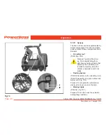
Recovery tank
(Fig. 19/1+5)
The waste water filter (Fig. 19/1) is located
under the recovery tank lid (Fig. 19/5) at
the top of the recovery tank and is con-
nected to the end of the suction pipe. It
filters large particle dirt from the waste
water and must be inspected or cleaned
daily, refer to Section 5.6.4.
Solution tank
(Fig. 19/2+4)
In order to fill fresh water and cleaning
agent, pivot up the lid of the solution tank
(Fig. 19/4) and lock it. The tank is filled
through the filling neck (Fig. 19/2) at the
top, refer to Section 5.5.1.
Lid lock
(Fig. 19/3)
The lock prevents the lid falling shut. To
lock the lid, move the bar and latch in
place. The lid lock functions in the same
way on the solution tank and recovery
tank.
Rear doors
(Fig. 19/8+11)
Open the rear doors to access the draining
hoses for waste water and solution.
Waste water draining hose
(Fig. 19/6)
The draining hose for waste water hooked
is in the left-hand rear door. Only drain off
waste water through this hose at an appro-
priate location, refer to Section 5.6.1.
Solution draining hose
(Fig. 19/7)
The draining hose for solution hangs to the
left of the suction turbines. Only drain off
the solution through this hose at an appro-
priate location, refer to Section 5.5.2.
Rear panel frame
(Fig. 19/9+10)
In order, for example, to access the flap
to clean the recovery tank, the rear panel
frame doors must be opened. To do this,
pull the lock lever (Fig. 19/9) up and open
the unlocked rear panel frame doors (Fig.
19/10).