3-17
PFC-6075 • 5403593 • Rev C • 2/13
From FACP or the previous
addressable device on the SLC loop
To the next addressable device
S+
S+
S-
S-
DWG #593-10
Connecting Analog Detectors
When installing analog detectors, such as a photoelectric smoke sensor (PSA), photo smoke/fixed heat detector (PSHA), heat
detector (FHA), or an analog combination type heat detector (RHA), use detector bases (
i.e. AB-6
). An analog detector activates
its response LeD when activated. An example of wiring an analog detector is shown below.
Analog Detector Wiring Example
Figure 10.
Connecting Addressable Modules
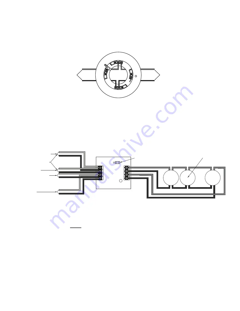
This section provides examples of wiring addressable modules, including Conventional Initiating Zones (CIZM-4), Miniature
Contact (MCM), Single Contact (SCM-4), Dual Contact Module (DCM-4), Twin Relay (TRM-4), Monitored Output (MOM-4),
Analog Relay (ARB), Analog Sounder Base (ASB), and Addressable Pull Station (APS) modules.
Conventional Initiating Zones (CIZM-4) Class A
CIZM-4, Class A
Figure 11.
Note: The resistance of external wiring shall be less that 100Ω.
The capacitance of external wiring shall be less than 1 micro farads.
From FACP or
Previous Module
To Next Module
From FACP
or Previous Module
To Next
Module
24-
24+
S-
S+
SLC Loop
LED
JP1
Select Style D
Conventional
Detector
_
+
_
+
_
+
Conventional Initiating Zone Module
Model No. CIZM-4
A-
A+
B-
B+
DWG #593-11
Notes
:
The resistance of external wiring shall be less than 100 ohms.
1.
The capacitance of external wiring shall be less than 1 micro F.
2.
In this style, the open circuit “
3.
trouble condition
” of IDC is latched at the control panel until system is reset.
Therefore, the system
MUST
be reset at the control panel after clearing the open circuit condition at the site.
Refer to the CIZM data sheet for information on compatible devices.
4.


