Porsche 911 GT3 Cup 2018 Скачать руководство пользователя страница 103


Version: 4/20/2018 

102 

Powertrain 

911 GT3 Cup (991 II) 

MY 2018 


Bearing assembly


Inserting the bearings requires the heating of the gearbox housing analogous to the 

setting of the adhesive connection (see above). All bearings must be inserted quickly 

before the housing has cooled off. To ensure the proper seat of the bearings, all 

bearings must be tapped with an appropriate tool after the housing has cooled off. 


Hot components  

Danger of burns  


Wear personal protective equipment. 
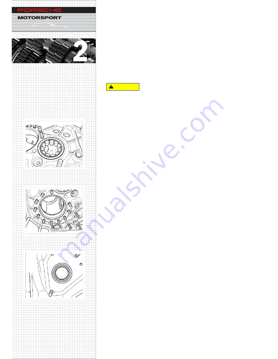
Drive shaft bearing


Dimensions:  

34x62x17 

Type: 

Cylinder roll bearing 


Tool:  

No. 1  


Pinion shaft cylinder roll bearing (outer ring) 

Dimensions: 

40x90x23 

Type: 

Cylinder roll bearing 


Tool:  

No. 3 


Input shaft/connecting shaft bearing 

Dimensions: 

30x37x16 

Type: 

Needle bearing 


Tool:  

No. 14 

2.9.1.12


2.9.1.10


2.9.1.11


Caution 
 

Содержание 911 GT3 Cup 2018

Страница 1: ...Technical manual 911 GT3 Cup 991 II MY 2018 ...

Страница 2: ... document should give you the opportunity to look up data settings und operating regulations and to facilitate maintenance or repair of the vehicle We wish you many sporting successes with your 911 GT3 Cup 991 II Customer Sport Dr Ing h c F Porsche Inc Motorsport Sales ...

Страница 3: ... on public roads and does not comply with the German Road Traffic Licensing Regulations Pictures descriptions and schematic drawings are used solely for illustrating the text We assume no responsibility for the completeness and conformity of the contents with the prevailing sporting codes Due to the constant improvement of our products and the related documentation at the time of your purchase a n...

Страница 4: ...Tel 49 0 711 911 85041 Mr Klaus Lenzner Tel 49 0 711 911 82423 Mr Christian Pelters Tel 49 0 711 911 89956 Mr Salvatore Scozzaro Tel 49 0 711 911 83738 Fax 49 0 711 911 89535 International One make Cup Series Assistent Mrs Nicole Nagel Tel 49 0 711 911 84900 Mr Tobias Hütter Tel 49 0 711 911 82616 Mr Christoph Hewer Tel 49 0 711 91186774 Fax 49 0 711 911 82920 Porsche Mobil 1 Supercup Mr Oliver Sc...

Страница 5: ... Warns against death or very serious injury which will certainly occur if the instructions are ignored Warns against death or very serious injury which may occur if the instructions are ignored Warns against minor injury if the instructions are ignored Warns against damage to property if the instructions are ignored Contains advisory information which makes the work procedure easier WARNING DANGER...

Страница 6: ... imperative that all persons carrying out repair and maintenance work on Porsche vehicles use their specialist knowledge to ensure that their own safety is not put at risk and that the procedure chosen will not have any negative effects on the vehicle especially with regard to safety It is therefore expressly specified that all work involved in the work procedures described should be carried out o...

Страница 7: ... 4 1 Schematic diagram 20 1 4 2 Thermostat 20 1 4 3 Coolant 21 1 4 4 Filling the cooling system 21 1 4 5 Racing at low temperatures 21 1 5 Intake system 22 1 5 1 Throttle valve 23 1 6 Working on the engine 24 1 6 1 Tightening specification for the flywheel 24 1 6 2 Valve timing 24 1 6 3 Removing and installing the crankshaft sealing ring flywheel side 25 1 6 4 Changing the poly V belt 30 1 6 5 Fue...

Страница 8: ...uation 63 2 2 4 Central release mechanism 64 2 3 Sequential six speed gearbox 65 2 3 1 Overview 65 2 3 2 Technical specifications 66 2 3 3 Gear set 67 2 3 4 Drive 70 2 3 5 Oil circuit 72 2 4 Gear shift mechanism 73 2 4 1 Gear shifting 74 2 4 2 Gear recognition 76 2 4 3 Emergency gearbox switch 76 2 4 4 Maintenance shift system 77 2 5 Drive shafts 78 2 5 1 Tightening instructions 78 2 6 Gearbox run...

Страница 9: ... 2 9 2 Gear housing pre assembly 106 2 9 3 Differential lid pre assembly 112 2 9 4 Pinion shaft bearing assembly 113 2 9 5 Pinion shaft 114 2 9 6 Pinion shaft position adjustment 116 2 9 7 Assembly of gear sets 118 2 9 8 Premounting shift drum 124 2 9 9 Oil pump assembly 125 2 9 10 Reverse idler gear 126 2 9 11 Locking sleeve 127 2 9 12 Shift rod and shift forks 128 2 9 13 Suction tube assembly 12...

Страница 10: ... 4 Rear axle shock absorber 190 3 3 5 Rear axle anti roll bar 192 3 3 6 Rear axle side part 195 3 4 Wheel alignment 196 3 4 1 Preparatory measures 197 3 4 2 Vehicle ride height measuring points 198 3 5 Steering system 199 3 5 1 Bleeding the steering system 202 3 6 Rims and tire 203 3 6 1 Rim 204 3 6 2 Tires 204 3 7 Brake system 205 3 7 1 General information 205 3 7 2 Front axle brake 208 3 7 3 Rea...

Страница 11: ... Roll cage 230 4 4 9 Recovery device 231 4 5 Aerodynamics 232 4 5 1 General 232 4 5 2 Rear wing 232 4 5 3 Additional aerodynamic improvements 232 4 6 Exterior mirrors 233 4 7 Roof 233 4 8 Air jack system 234 4 9 Doors 236 4 10 Trunk and engine lid 236 4 10 1 Trunk lid 236 4 10 2 Engine lid 236 4 11 Windows 237 4 11 1 Installing and removing the windshield 237 4 11 2 Preparing the window cutout for...

Страница 12: ...d repair kit 283 4 16 1 Thread repair of chassis bolt connections 284 4 17 Installing roof assembly 301 5 Interior 303 5 1 General 303 5 2 Drivers safety 304 5 2 1 Seat 304 5 2 2 Seat rail tightening torques 306 5 2 3 Bucket seat tightening torques 307 5 2 4 Padding system 308 5 3 Steering wheel 309 5 4 Cockpit ventilation 310 6 Electrical system 311 General 311 Power supply 311 6 2 1 Battery 311 ...

Страница 13: ... 6 7 1 General information 328 6 7 2 Race page 1 330 6 7 3 Race page 2 331 6 7 4 Race page 3 332 6 7 5 Practice page 333 6 7 6 Warmup page 335 6 7 7 Vitals page 336 6 7 8 Control page 338 6 7 9 Chassis page 340 6 7 10 Pit Speed 344 6 7 11 Alarm displays 345 6 7 12 Trackmap page 350 6 7 13 Diagnose page 350 6 7 14 Position of balance bar 352 Lights 353 Data bus system 354 Wiring harness 356 Ground ...

Страница 14: ...Engine tightening torques 374 7 1 8 Engine runtime 375 7 2 Fuel system 376 7 2 1 Fuel 376 7 2 2 Fuel extraction 378 7 3 Power transmission 380 7 3 1 Gearbox 380 7 3 2 Clutch 383 7 3 3 Paddle shift 386 7 3 4 Drive shafts 388 7 4 Chassis 389 7 4 1 Wheel nut 389 7 4 2 Locking piece 390 7 4 3 Wheel bearings 391 7 4 4 Wheel hub 391 7 4 5 Wheel rim 391 7 4 6 Brake system 392 7 4 7 Replacing the piston s...

Страница 15: ...ning in front lid 442 8 4 2 8 4 2 Fuel draining system 444 8 5 Taxi seat 449 8 5 1 8 5 1 Chassis preparation for console fixation 449 8 5 2 8 5 2 Fixation six point safety belt 451 8 5 3 8 5 3 Assembling the footwell cover 453 8 5 4 8 5 4 Repositioning vehicle electrical system control unit IPS 454 8 5 5 8 5 5 Position the seat bracket at the rear position 456 8 5 6 8 5 6 Installing the seat shell...

Страница 16: ...Version 4 20 2018 911 GT3 Cup 991 II MY 2018 15 Preface 8 11 Battery charging cable 471 8 12 Suspension travel sensor 472 ...

Страница 17: ...Version 4 20 2018 911 GT3 Cup 991 II MY 2018 16 Preface ...

Страница 18: ...rol for the intake and exhaust valves and rigidly mounted valve levers for valve actuation The oil supply for the connecting rod bearings is ensured by the central oil supply to the crankshaft Also new is the demand controlled oil pump with integrated centrifuge for oil defoaming The engine features dry sump lubrication with an oil tank mounted on the engine side The oil is cooled by an oil water ...

Страница 19: ...engine specifications Number of cylinders 6 Type Flat six engine Valves per cylinder 4 Displacement 3 996 cc Bore 102 0 mm 4 inches Stroke 81 5 mm 3 2 inches Compression Approx 13 3 1 Max engine speed 8 500 rpm Cooling Water cooled Lubrication Dry sump lubrication demand controlled oil pump Oil water heat exchanger ...

Страница 20: ...em for controlling the engine temperature 1 3 1 Oil level measurement On the 911 GT3 Cup 991 the oil level is measured electronically by means of a level sensor in the oil tank There is no dipstick To ensure a correct measurement the engine must be at operating temperature coolant temperature 80 C 176 F See Section 7 1 1 3 2 Filling capacities Improper adding of engine oil Risk of damage to the en...

Страница 21: ...xchanger 10 Oil filter 11 Pressure temperature sensor 12 Piston oil spray jet switching valve 13 Crankshaft 14 Piston 15 Piston oil spray jets 16 Chain tensioner 17 Camshaft control valve 19 Camshaft intake 20 Camshaft exhaust 21 Camshaft bearing 22 Valve lever with oil spray jets 23 Oil collection duct 24 Camshaft controller 25 Oil filler neck 26 Oil tank 27 Oil level sensor 28 Air oil separator ...

Страница 22: ...ds The oil for the connecting rod bearings is not routed to the connecting rod via the main bearings here in the conventional way but rather supplied centrally from the main oil gallery to the crankshaft via a line This achieves a more stable oil supply to the connecting rod bearings with less loss 1 3 6 Oil mist separator The oil tank vent is routed into the intake system through an oil mist sepa...

Страница 23: ...he respective units to operating temperature and maintain them there There is a pressure relief valve fitted in the cap of the expansion tank that opens above an overpressure of 1 4 bar 203 psi max volume flow 3L min The system must be checked if it is losing coolant or a leak is suspected Hazet provides a tester for this that pressurizes the cooling system in order to locate any possible leakage ...

Страница 24: ... corrosion agent protects the water carrying parts against corrosion reduces cavitation lubricates the water pump and increases the boiling point of the cooling water For races as part of a Formula 1 event the coolant must be replaced as described below Approx 20 liters 21 1 qts of water plus at least 2 liters 2 1 qts of anti corrosion agent Porsche spare part no 997 106 907 90 Filling capacity 22...

Страница 25: ...Version 4 20 2018 Engine 24 911 GT3 Cup 991 II MY 2018 Engine 1 5 Intake system 1 5 1 The new intake bridge has been made from plastic to save weight and lower the center of gravity ...

Страница 26: ...lectrical signal from the gas pedal is converted into an opening angle by an electrical servo motor in the throttle valve The Start button is blocked for 3 seconds after the ignition is switched on to prevent interference with the throttle valve calibration The throttle valve does not need to be adjusted After the ignition is switched on the throttle valve opens and closes automatically and in thi...

Страница 27: ...ews in diagonally opposite sequence with a 90 angle of rotation 1 6 2 Valve timing The valve timing does not need to be adjusted the position of the camshafts is detected by the engine control and automatically readjusted to the optimum setting Bad engine start properties Adjustment of valve timing by car spinning The engine can turn anticlockwise in case of car spinning s The cam shaft positions ...

Страница 28: ... for crankshaft sealing ring Porsche spare part no 9699 3 This tool can be ordered in the Porsche Dealership Removal 1 Drain the engine oil Removal of the sealing ring Damage to the crankshaft engine block Leakage in the engine Do not lever out the sealing ring The sealing ring must only be removed using an impact pull off device 2 Prick punch the sealing ring centrally at two positions offset by ...

Страница 29: ...ter the metal ring is pulled off Removal of the remaining sealing ring Damage to the crankshaft engine block Leakage in the engine Do not lever out the remaining sealing ring The remaining sealing ring must only be removed using an impact pull off device or tapping screws 6 Carefully remove drilling chips 7 Using a Ø 2 mm 0 08 inches bit carefully drill another two holes arrows as far into the cor...

Страница 30: ... a Screw the threaded tip of the impact pull off device alternately into the bore holes and pull the sealing ring off evenly 1 6 3 3 b Screw in two tapping screws and pull the sealing ring off evenly using the claw sleeve from a slide hammer kit 1 6 3 4 9 Carefully remove chips and oil residue at the crankshaft bore hole ...

Страница 31: ...aphtha Unscrew the press in tool Porsche spare part no 9699 3 Figure 1 6 3 5 Slide the sealing ring with red assembly protection onto the base plate Grease the outside of the sealing ring Figure 1 6 3 6 and Figure 1 6 3 7 Secure the base plate to the crankshaft using two hexagon socket head bolts a f 8 arrows in Figure 1 6 3 7 Screw the mounting bell onto the base plate Damage to the sealing ring ...

Страница 32: ...to take measurements at four points from the crankcase flange to the flat part of the steel ring arrows Measured depth is approx 4 5 mm 0 18 inches Maximum permissible inclined position is 0 5 mm 0 02 inches If the comparative values exceed the maximum difference press the sealing ring on again using the insertion tool Information 1 6 3 8 ...

Страница 33: ...lt Unscrew the retaining bracket 2x M6x16 hexagon round head bolts 1x M10x135 hexagon head bolt Figure 1 6 4 1 Remove the spacer Figure 1 6 4 2 Changing the belt Relieve the tension on the belt To do this turn the a f 30 belt tensioner clockwise arrow in Figure 1 6 4 3 Remove the belt Fit the new belt Figure 1 6 4 4 shows the routing of the belt Loosen the tensioner to allow the belt to assume the...

Страница 34: ...st always be replaced following disassembly Mounting specification for the high pressure line The assembly specification is the same for both cylinder banks Fit the line always use a new line Screw on the union nut by 2 3 turns the line must still be freely movable Tighten the M6 bolt item 1 to 7 Nm 5 2 ft lb Tighten the union nut item 2 to 25 Nm 18 4 ft lb WARNING 1 6 5 1 2 1 ...

Страница 35: ... 2 Service cover on valve cover M5x20 6 5 Nm 4 8 ft lb Intake distributor on cylinder head M6x35 13 Nm 9 6 ft lb Holder tank drain on intake distributor M6x12 10 Nm 7 4 ft lb Holder fuel pipe low prs on intake distributor M8x12 20 Nm 14 8 ft lb Knock sensor M8x35 23 Nm 17 ft lb 2 Nm 1 5 ft lb Spark plugs install max five times M12x1 25 25 Nm 18 4 ft lb Ignition coil fastening M6x16 10 Nm 7 4 ft lb...

Страница 36: ... 44 3 ft lb Engine strut on crankcase M10 60 Nm 44 3 ft lb Heat protection on engine carrier M5x12 5 Nm 3 3 ft lb Underbody fastening M6x12 12 Nm 8 8 ft lb Underbody fastening M8x20 23 Nm 17 ft lb Oil tank Oil tank on crankcase M8x35 23 Nm 17 ft lb Oil tank on intake distributor M8x30 23 Nm 17 ft lb V band clamps on oil tank M6x25 4 Nm 2 6 ft lb Oil drain plug on oil tank M18x1 5 30 Nm 22 1 ft lb ...

Страница 37: ...t Variants with a muffler with additional front mufflers as well as without any muffler are available All variants have exhaust manifolds with catalytic converters each 100 cells The exhaust system is always mounted on the engine System with rear muffler 1 8 1 System without muffler Supercup system 1 8 2 System with front muffler and rear muffler 1 8 3 ...

Страница 38: ...t system configuration Measuring height Distance to exhaust pipe Angle to exhaust pipe Engine speed rpm Supercup exhaust Center silencer Center silencer side silencers Accoustic power dB A Accoustic power dB A Accoustic power dB A 1 2 m 15 m 90 8500 full load 114 2 106 1 99 3 1 2 m 10 40 m 90 8500 full load 116 6 107 6 101 9 Overview stationary measurements Measurment parameters Exhaust system con...

Страница 39: ...911 GT3 Cup 991 II MY 2018 Engine 1 9 Mounting front muffler Prelimnary work Remove rear cover Let the exhaust system cool down Hot components Risk of burns Allow hot components to cool down Wear protective clothing 1 9 1 Caution ...

Страница 40: ...Version 4 20 2018 39 Engine 911 GT3 Cup 991 II MY 2018 Engine Pre mount the holder of the front muffler Tighten the screw 1 Figure 1 9 2 Torque 20 Nm 1 1 9 2 ...

Страница 41: ...he front muffler an adaption oft he heat shiled below the rearlight is required For this purpose an additional heat shield 1 Figure 1 9 3 must be attached to the body Drill the marked points Figure 1 9 4 with a drill Ø 9 mm 0 358 inch Insert the blind rivet nuts with the rivet tool NOTE 1 9 3 ...

Страница 42: ...T3 Cup 991 II MY 2018 Engine Insert the new heat shield 1 and mark the drill points 2 Figure 1 9 4 View from below Drill the marked points Figure 1 9 4 with a drill Ø 9 mm 0 35 inch Insert the blind rivet nuts with the rivet tool 1 9 4 ...

Страница 43: ... 991 II MY 2018 Engine Position the heat shiled 1 to secure with two torx screws 2 Figure 1 9 5 Torque 10 Nm After the screws are tightened an additional heat protection yellow marking must be glued over the screw 1 Figure 1 9 6 1 9 5 1 9 6 ...

Страница 44: ...n the holder on the cylinder head Tighten the screws 1 by hand The holder must remain displaceable Pess the holder with slight force in thre direction of the motor Figure 1 9 7 arrow so that it rests evenly on both screw shafts Tighten the two screws 1 Torque 23 Nm 1 9 7 ...

Страница 45: ...attached to the vehicle and has little freedom of movement due to the decoupling elements Install the lower connecting pipe with the ball clamp on the exhaust manifold Attach the ball clamp only hand tight The connecting pipe must still move freely Figure 1 9 9 Information 1 9 8 1 9 9 ...

Страница 46: ...gine Attach the connecting pipe cleanly tot he front muffler Place the v band clamp on the front and rear Tigthen both halves evenly Figure 1 9 10 Observe the orientation oft he v band clamp Tigthen the screws oft he v band clamp Torque 5Nm NOTE 1 9 10 1 9 11 ...

Страница 47: ...Engine Insert the upper connecting pipe into the rear muffler Fit the connecting pipe upper on the front muffler Figure 1 9 12 arrows Align the connecting pipe parallel tot he connection oft he front muffler and install the clamp Figure 1 9 13 1 9 12 1 9 13 ...

Страница 48: ... 20 2018 47 Engine 911 GT3 Cup 991 II MY 2018 Engine Observe the orientation of the ball clamp Tighten the two screws oft the ball clamp by hand The front muffler must be movable Figure 1 9 15 NOTE 1 9 14 1 9 15 ...

Страница 49: ...ing and fixing the front muffler the conditions of the connections should be observed Figure 1 9 16 The rear muffler is firmly connected to the engine bracket NOTE 1 9 16 1 Ball clamp loose 2 V band clamp fixed 3 Ball clamp loose 4 Connection loose 5 Fron muffler bracket fixed ...

Страница 50: ...ion oft he engine Figure 1 9 17 arrow Fully eliminate the freedom of movement and hold the front muffer in position Tighten the screw 1 of the ball clamp torque 18 Nm Tighten the screw 2 of the ball clamp torque 13 Nm Tighten the nuts 3 on the connecting flange torque 23 Nm Observe the distance to the heat protection parts NOTE 1 9 17 ...

Страница 51: ...r to the heat protection parts must not be less than 6 mm 0 23 inch If the muffler comes into contact with the heat shield during travel the insulation can be damaged The insulation effect is reduced Thermal overloading of surrounding components may occur NOTE 6 mm 0 23 inch 6 mm 0 23 inch 1 9 18 ...

Страница 52: ...ween the connecting pipes at the narrowest point should not be less than 8mm 0 31 inch Figure 1 9 19 If the pipes touch during the ride the insulation may be damaged The insulation effect is reduced Thermal overloading of surrounding components may occur NOTE 8 mm 0 31 inch 1 9 19 ...

Страница 53: ...Version 4 20 2018 Engine 52 911 GT3 Cup 991 II MY 2018 Engine Remove the old seals 1 from the side heat shield Figure 1 9 20 Fit the new seal 2 Figure 1 9 21 1 9 20 1 9 21 ...

Страница 54: ...Figure 1 9 22 View from the rear When installing the side heat protection 1 make sure that the edge of the vehicle safe heat protection 2 is not folded or damaged The correct fit of the two heat shields is important for the function of the overall system Fig 1 9 23 front view NOTE 1 9 23 1 9 22 ...

Страница 55: ...Version 4 20 2018 Engine 54 911 GT3 Cup 991 II MY 2018 Engine Press the heat shield 1 upwards until it rests against the seal 2 Figure 1 9 24 1 9 24 ...

Страница 56: ...ont silencers and the heat protection should not be less than 6 mm 0 23 inch If the muffler comes into contact with the heat shield during travel the insulation can be damaged The insulation effect is reduced Thermal overloading of surrounding components may occur NOTE 6 mm 0 23 inch 1 9 25 ...

Страница 57: ...Version 4 20 2018 Engine 56 911 GT3 Cup 991 II MY 2018 Engine 1 10 Mounting wheel arch 1 10 1 1 10 2 Cut away the red marked area 15mm ...

Страница 58: ...Version 4 20 2018 57 Engine 911 GT3 Cup 991 II MY 2018 Engine 1 10 3 Position the wheel arch mark centre of bore 1 Drill hole using a 9 0 mm drill bit Insert blind rivet nut in the frame 1 10 4 ...

Страница 59: ...Version 4 20 2018 Engine 58 911 GT3 Cup 991 II MY 2018 Engine 1 10 5 Position the wheel arch Mark centre of bore 1 Drill hole using a 9 0 mm drill bit Insert blind rivet nut in the rear bodywork ...

Страница 60: ...Version 4 20 2018 59 Engine 911 GT3 Cup 991 II MY 2018 Engine 1 10 6 Fasten wheel arch 1 SELF TAPPING SCREW ST4 8x19 3 Nm 2 IN 6RD FLSH_SHR M6x12 3 Nm 3 IN 6RD FLSH_SHR M6x12 3 Nm 4 6KT MU M6 S 10 Nm ...

Страница 61: ...outlet 1 3 Phase Sensor intake 4 Fuelpress Sensor 5 Crankcasepress sensor 6 Manifold pressure and temp Sensor 7 Knock Sensor 2 8 Cooling water temp Sensor 9 Lambda probe 2 1 Knock Sensor 2 Fuel press rail Sensor high pressure 1 3 Engine oil temp and pressure Sensor 4 Oil level tank 5 Fuel press rail Sensor high pressure 2 ...

Страница 62: ...arranty voided Do not exceed an engine speed of 8 500 rpm The engine of the 911 GT3 Cup 991 II which is based on the 991 GT3 RS standard production unit is designed for a maximum engine speed of 8 500 rpm Component Running time Stop choc elements of the exhaust system only installed in exhaust systems without muffler or with front mufflers 60 h Engine 100 h NOTE ...

Страница 63: ...ccordance with the table below if the maximum engine speed of 8 500 rpm is exceeded Engine speed Duration Overhaul 8 500 9 000 rpm After 60 hours 9 000 9 500 rpm More than 6 seconds Immediate inspection on the test stand 9 500 rpm More than 2 seconds Immediate engine overhaul 10 000 rpm First time the engine speed is exceeded Immediate engine overhaul ...

Страница 64: ...account the pneumatic actuation by means of the compressed air system To increase the ruggedness and the running time the gearbox is refined In addition the gearbox is equipped with a limited slip differential an oil filter and an oil water heat exchanger for cooling Despite the compact design of the gearbox accessibility to the individual components has been enhanced This is a significant improve...

Страница 65: ...ering loading and unloading etc 2 2 1 Installation instructions Make sure that the wings of the multiple disk clutch sintered disks 1 are stacked and aligned A if possible Lightly grease the gear teeth of the hub B and move the clutch disks back and forth on the connecting shaft gear teeth until the hub moves smoothly on the shaft If required remove excess grease Contaminated oily clutch linings C...

Страница 66: ...ive fluids Danger of chemical burns Wear personal protective equipment Ensure good ventilation Avoid contact with corrosive fluid If you do come into contact wash off immediately with plenty of warm water and contact a doctor if necessary Depress the clutch pedal 2 to 3 times and keep it depressed Shortly open the vent valve rear cross member illustration 2 2 3 1 the clutch pedal has to be depress...

Страница 67: ...se lever Loss of clutch function Do not allow the seal to come into contact with engine oil or transmission oil The seal must only be fitted using the special tool from Sachs Also make sure to remove oil residues from your hands and the working environment before handling the seal this also applies to engine oil and other oils According to the manufacturer the seal is compatible only with hydrauli...

Страница 68: ...in 911 GT3 Cup 991 II MY 2018 2 3 Sequential six speed gearbox 2 3 1 Overview 2 3 1 1 1 Limited slip differential 2 Connecting shaft 3 Drive shaft 4 Gear shift drum 5 Cross shaft 6 Pinion shaft 7 Gear shift mechanisms 2 1 4 5 6 3 7 ...

Страница 69: ... 3 17 qt Weight 70 kg 154 lb Gear Teeth i_gear i_const i_bevel crown gear i_total 1 13 41 3 154 2 412 1 571 11 951 2 17 40 2 353 2 412 1 571 8 916 3 19 36 1 895 2 412 1 571 7 181 4 19 29 1 526 2 412 1 571 5 782 5 24 30 1 250 2 412 1 571 4 737 6 34 35 1 029 2 412 1 571 3 899 Reverse 16 37 2 313 2 412 1 571 8 765 Constant 17 41 2 412 3 789 bevel crown gear 14 22 1 571 3 789 ...

Страница 70: ...th fixed gears the pinion shaft 6 with idlers a cross shaft with constant ratio 5 and the limited slip differential 1 Connecting shaft The connecting shaft 1 is the element that connects the clutch to the drive shaft It transfers the torque generated by the engine directly to the fixed gears of the drive shaft 1 2 3 3 2 1 5 6 3 ...

Страница 71: ...pecial feature is the combination of cylindrical rollers and angular contact ball bearings directly in front of the bevel gear This bearing arrangement directs the occuring forces into the housing in the best possible way The pinion shaft accommodates all idlers of the gear pairs as well as the sliding sleeves which are responsible for positive engagement 2 3 3 4 1 Fixed gear 1st gear 2 Fixed gear...

Страница 72: ... by 90 is located behind the pinion shaft and is used for changing the direction of the torque The crown gear of the cross shaft is driven by the bevel gear of the pinion shaft The torque is transmitted by means of the opposing spur gear teeth to the limited slip differential located above it 2 3 3 5 1 ...

Страница 73: ...om the drive shaft to the pinion shaft The direction of the torque speed is changed from the longitudinal to transverse direction by means of the cross shaft with constant ratio The final drive ratio transmits the torque through the limited slip differential to the axle flanges and finally through the axle shafts to the driving wheels Direction of rotation traction Shaft movement traction Shaft mo...

Страница 74: ...e transmit the torque to the two cross pin bolts 2 The differential gears pivoted on these bolts drive the output shaft flanges by means of the lateral bevel gears Depending on the torque gradient traction thrust the cross pin bolts move the pressure pieces out and press the clutch disks 4 the pressure plates 3 and the cup springs 5 together Component overview 2 3 4 3 Basic blocking torque The bas...

Страница 75: ...1 is located on the right side of the gearbox Oil cooling The gearbox is provided with a separate oil water heat exchanger 2 for heating and cooling the gearbox oil The heat exchanger is fitted externally on the upper side of the gearbox The internal oil pump is driven by the idler of the 1st gear on the pinion shaft the cooling oil supply depends on the engine speed An oil filter located in the g...

Страница 76: ...sensor failure Refer to chapter 2 4 3 Paddle Shift The paddle shift system is used by the driver to change gears and to protect the drive train against incorrect handling Shift paddles on the steering wheel pass electrical signals to the Bosch engine control unit when they are actuated The shift request is evaluated in the Bosch ECU and transferred to the APS control unit The compressor integrated...

Страница 77: ...ocess may still allow over revving Therefore avoid blocked wheels Connenction of the components Valve block 2 4 3 1 Upshift 2 Downshift Shift cylinder 2 4 4 1 Upshift 2 Downshift 2 4 1 Gear shifting Gear shifting is initiated by the paddles on the steering wheel Different parameters e g velocity rpm are checked by means of the CAN bus to determine whether gear shifting is possible If this is the c...

Страница 78: ...hrust condition In addition the following conditions must be met accelerator pedal 0 and the throttle position must be less than 20 Functional testing at standstill When performing a functional test the following conditions have to be met Engine at standstill neng 0 Vehicle velocity 5 km h 3 mph Up down shifting with and without clutch is possible Up shifting Down shifting R N N 1 1 6 6 1 1 N N R ...

Страница 79: ...ntiometer has to point to the bottom position when mounted correctly 2 4 3 Emergency gearbox switch In case of failure of certain sensors that normally ensure the correct operation of the gear shift system an emergency program may be enabled by pressing the Emergency Gearbox switch The emergency program is automatically enabled in case of the following malfunctions 1 Clutch pressure sensor defecti...

Страница 80: ...r the valve block and the shift cylinder Small Service Once p a Max 10 000 km Max 10 h compressor run time Big Service Every two years Max 20 000 km Max 20 h compressor run time Contact data MEGA Line Racing ELECTRONIC GmbH Haunersdorf Str 3 D 93342 Saal a d Donau Phone 49 9441 6866 0 Fax 49 9441 6866 11 E Mail info mega line de ...

Страница 81: ... for joint on wheel side 150 g 5 3 ounces Grease quantity for joint on gearbox side 120 g 4 2 ounces Service partner addresse GKN Service International GmbH see chapter 7 9 2 5 1 Tightening instructions 1 Tighten all bolts to 30 Nm 22 1 ft lb in the specified order figure 2 5 1 2 Tighten all bolts to 60 Nm 44 3 ft lb in the specified order figure 2 5 1 3 Tighten all bolts to 90 Nm 66 4 ft lb in th...

Страница 82: ...ox housing oil pump 6KT MU M6 4 10 Nm Gearbox housing oil suction pipe 6KT MU M6 1 10 Nm Gearbox housing gear shift drum 6KT MU M6 2 10 Nm Gearbox housing thrust bearing with stop 6KT MU M8 1 25 Nm Gearbox housing thrust bearing with stop 6KT MU M6 1 10 Nm Gearbox housing oil bore cap VSHL SHR M10x1 3 15 Nm Gearbox housing oil bore cap VSHL SHR M12x1 5 3 9 Nm Gearbox housing central release mechan...

Страница 83: ...haft end 4 point bearing lock nut M32x1 25 1 50 Nm 60 then untighten 50 Nm 60 Gearbox housing oil spray pipe ZYL SHR M5x10 3 6 Nm Gearbox housing oil spray pipe ZYL SHR M5x16 3 4 Nm Gearbox housing oil spray pipe ZYL SHR M5x15 2 6 Nm Gearbox housing oil spray pipe 6KT MU M6 1 10 Nm Gearbox housing oil spray pipe spring support M16x1 5 2 35 Nm Gearbox housing oil spray pipe 6KT MU M6 1 10 Nm Z diff...

Страница 84: ...d to component damage Preliminary work Drain transmission oil Hot fluid Danger of scalding Let the fluid cool down Wear personal protective equipment 2 8 1 Dismantling of hang on parts Dismantle axle shaft flanges with panel puller 1 Figure 2 8 1 1 Remove the shaft sealing ring of the input flanges with the assembly lever Figure 2 8 1 2 Remove gear potentiometer 2 Remove shift control 3 Remove the...

Страница 85: ...ment Ensure good ventilation Avoid contact with corrosive fluid If you do come into contact wash off immediately with plenty of warm water and contact a doctor if necessary 2 8 2 Gear housing dismantling Remove the locking ring 1 of pinion shaft and rotation prevention Figure 2 8 2 1 By twisting the pinion shaft engage gear 1 and fix the drive shaft in place with tool no 19 Figure 2 8 2 2 Loosen t...

Страница 86: ...O ring from the shift rod Figure 2 8 3 1 Pull out the shift rod toward the top ensure that the shift forks do not drop out of the sleeves Remove the shift forks Remove the reverse gear shift fork Remove the locking ring drive shaft Remove the pinion shaft nut Remove gearwheels needle bearing and guide sleeves mark the installation position and rotational direction of the gearwheels and sleeves 2 8...

Страница 87: ...the shift drum against twisting with an open end wrench and loosen the shift drum nut with socket Porsche spare part No 997 450 306 00 Figure 2 8 4 2 2 8 5 Dismantling the locking sleeve Loosen the nut 2 and 3 and the screw 1 of the locking sleeve and remove the locking sleeve Figure 2 8 5 1 Remove the reverse idler gear 3 with the axle 4 Figure 2 8 5 2 2 8 4 1 2 8 4 2 2 8 5 1 2 8 5 2 ...

Страница 88: ...ved before taking out the shift module because the shift module cannot be pulled out otherwise Oil pump Remove the locking ring 1 of the oil pump gearwheel Figure 2 8 6 3 Pull off the gearwheel Keep in mind the insert washers between shaft and gearwheel Loosen the fastening nuts of the oil pump and pull off the oil pump Oil filter element Remove the locking ring 5 Remove the closure cap 3 with a p...

Страница 89: ...closure cap with the panel puller Figure 2 8 7 1 Remove the cross shaft lid catch Open the cross shaft lid with the assembly lever Figure 2 8 7 2 Remove adjusting disk P2 of the anti lash plate Figure 2 8 7 3 Clamp tool no 49 into the vice and insert the cross shaft Figure 2 8 7 4 Fix the cross shaft in place with the nut arrow 2 8 7 4 2 8 7 3 2 8 7 2 2 8 7 1 ...

Страница 90: ...ring is behind it Remove the bearing shell of the four point bearing Carefully tap out the shaft of the cross shaft lid with a rubber hammer Mechanical hydraulic or pneumatic press Risk of crush injuries Read specific safety information for the press Check that the press is working perfectly before use particularly the safety components Press the ring gear out with the hydraulic press Put the ring...

Страница 91: ...Read specific safety information for the press Check that the press is working perfectly before use particularly the safety components Push the cage out of the cylinder roll bearing cross shaft with tool no 44 Figure 2 8 7 8 Hot components Danger of burns Wear personal protective equipment Heat the cross shaft lid 1 at 130 C 266 F for 30 minutes Take the outer ring of the cylinder roll bearing 2 o...

Страница 92: ...ake out the pinion shaft through the assembly opening Mechanical hydraulic or pneumatic press Risk of crush injuries Read specific safety information for the press Check that the press is working perfectly before use particularly the safety components Press out the cylinder roll bearing of the pinion shaft with tool no 44 Figure 2 8 8 2 See 2 8 7 cross shaft dismantling 2 8 8 2 2 8 8 1 WARNING ...

Страница 93: ...r of burns Wear personal protective equipment Heat the differential lid at 130 C 266 F for 30 minutes Remove the bearing 2 without applying great force Remove the differential from the gearbox housing Figure 2 8 9 3 Loosen the differential lid screws evenly using a crisscross pattern Screw two panel pullers on the differential lid and separate the lid from the housing The inner threads in the diff...

Страница 94: ...hemical burns Wear personal protective equipment Ensure good ventilation Avoid contact with corrosive fluid If you do come into contact wash off immediately with plenty of warm water and contact a doctor if necessary Remove the central clutch operator Figure 2 8 10 1 2 8 11 Connecting shaft dismantling Drive out the connecting shaft with the panel puller Figure 2 8 11 1 2 8 10 1 2 8 11 1 WARNING 2...

Страница 95: ...g Take out the drive shaft locking ring 1 Use the shortened locking ring pliers Figure 2 8 12 2 The handles of the pliers are shortened so that the pliers can be used inside the gearbox housing Take out the thrust plate 2 Remove the drive shaft 3 from the gearbox housing 2 8 12 1 2 8 12 2 ...

Страница 96: ... components Danger of burns Wear personal protective equipment Heat the gearbox housing at 130 C 266 F for 30 minutes Remove the outer rings of the bearings in the housing The outer rings of the bearing can be dismantled without applying great force Outer ring of the drive shaft bearing Figure 2 8 13 2 Screw the pinion shaft retaining frame 4 off the gearbox housing Take out the four point bearing...

Страница 97: ... out the connecting shaft needle bush in the direction of the arrow with tool no 46 Figure 2 8 13 7 Gear housing Remove the baffle of the bearings 4 Hot components Danger of burns Wear personal protective equipment Heat the gear housing at 130 C 266 F for 30 minutes Push out the outer ring of the drive shaft 2 Push out the outer ring of the pinion shaft 3 Push out the ball bearing of the shift dru...

Страница 98: ...mplete assembly instructions in mind Mounting studs Before mounting the studs the thread holes must first be cleaned thoroughly with petroleum benzine brake cleaner and afterwards with acetone The gearbox housing and the gear housing must finally be blown out with oil free compressed air A special installation tool must be used to screw in the studs The studs are not tightened with a turning torqu...

Страница 99: ...ite 2701 green Thread position Screw in short thread Starter studs 1 Dimensions M10x22 Projection 24 mm 0 94 Adhesive Loctite 2701 green Thread position Screw in short thread Gear housing connection studs green Dimensions M8x50 Projection 50 mm 1 97 Adhesive Loctite 2701 green Thread position Screw in short thread 2 9 1 3 2 9 1 4 2 9 1 5 ...

Страница 100: ...mm 5 71 Adhesive Loctite 2701 green Thread position Screw in long thread Oil pump studs 2 Dimensions M6x28 Projection 27 mm 1 06 Adhesive Loctite 2701 green Thread position Screw in short thread Screw in suction tube screw stud 1 Dimensions M6x10 Projection 9 mm 0 35 Adhesive Loctite 2701 green Thread position Screw in long thread 2 9 1 6 ...

Страница 101: ...ad position Screw in long thread Shift drum stud 2 Bushing must first be pressed in Dimensions M6x35 Projection 29 mm 1 14 Adhesive Loctite 2701 green Thread position Screw in long thread Locking sleeve screw connection stud Dimensions M8x30 Projection 27 5 mm 1 083 Adhesive Loctite 2701 green Thread position Screw in long thread 2 9 1 7 Information ...

Страница 102: ...erator screw connection stud arrow Dimensions M6x18 Projection 19 mm 0 75 Adhesive Loctite 2701 green Thread position Screw in long thread Injection tube stud Dimensions M6x10 Projection 10 mm 0 39 Adhesive Loctite 2701 green Thread position Screw in long thread 2 9 1 9 2 9 1 8 ...

Страница 103: ...e the proper seat of the bearings all bearings must be tapped with an appropriate tool after the housing has cooled off Hot components Danger of burns Wear personal protective equipment Drive shaft bearing Dimensions 34x62x17 Type Cylinder roll bearing Tool No 1 Pinion shaft cylinder roll bearing outer ring Dimensions 40x90x23 Type Cylinder roll bearing Tool No 3 Input shaft connecting shaft beari...

Страница 104: ... ring 1 at a 180 offset to the opening 2 Outer ring of cross shaft bearing Dimensions 50x90x20 Type Cylinder roll bearing Tool No 6 Locking ring 90x2 5 Insert locking ring at a 90 offset to the opening Needle bearing for long axle flange 1 Dimensions 40x55x22 Type Needle bearing Tool No 9 Press in all the way to the stop 2 9 1 14 2 9 1 13 2 9 1 15 Information Information ...

Страница 105: ... 911 GT3 Cup 991 II MY 2018 Differential cylinder roll bearing in the gearbox housing Dimensions 59 5x90x23 Type Cylinder roll bearing Tool No 8b With locking ring Insert locking ring at a 90 offset to the opening 2 9 1 16 Information ...

Страница 106: ...the housing see 2 9 1 Pre assembly bearing assembly Pressing in the bushing for the oil filter 1 Adhesive Loctite 638 Press in up to the limit Gearbox housing gear housing screw connection bushing 12x6x16 Press in fitting sleeve Pinion shaft retaining frame locating pins Press in up to the limit Attach perforated panel of clutch bleeding and secure with locking ring 2 9 1 17 2 9 1 18 Caution ...

Страница 107: ... plugs must be sealed with surface sealant Loctite 574 Apply sealant thinly on the thread surface for this Oil hole closure Dimensions M12x1 5 alu Torque 9 Nm 6 6 ft lb Attach with sealing ring 12x18 Plug without pressure sensor Dimensions M10x1 Torque 9 Nm 6 6 ft lb Use sealing ring 10x14x1 2 9 1 20 2 9 1 19 ...

Страница 108: ...on 4 20 2018 107 Powertrain 911 GT3 Cup 991 II MY 2018 Mounting hydraulic connections for the clutch Use Loctite 574 orange Bleeding 2 With Sealing ring Pressure line 1 With Sealing ring 2 9 1 21 Information ...

Страница 109: ...t running of the transmission The gear housing must finally be blown out with compressed air Hot components Danger of burns Wear personal protective equipment The studs must be cleaned thoroughly with petroleum benzine After the studs are inserted the gear housing has to set in an oven for approx 40 minutes at 130 C 266 F Screwing in the gear housing studs Heat exchanger studs green Dimensions M6x...

Страница 110: ...ad position Screw in long thread Threaded pin of the baffle Dimensions M5x20 12 9 Projection 7 mm 0 27 Adhesive Loctite 2701 green Shift module screw connection stud 26 Dimensions M6x18 Projection 17 mm 0 67 Adhesive Loctite 2701 green Thread position Screw in long thread One hole top right is left for one bushing 27 2 9 2 2 2 9 2 3 2 9 2 4 Information ...

Страница 111: ...ew in long thread Gearbox bracket stud 2 Top Dimensions M10x52 10 9 Projection 45 mm 1 77 Adhesive Loctite 2701 green Thread position Screw in short thread Press in fitting sleeve 1 Porsche spare part No 991 301 641 9B up to the limit Bottom Dimensions M10x45 10 9 Projection 45 mm 1 77 Adhesive Loctite 2701 green Thread position Screw in short thread 2 9 2 6 2 9 2 5 Information ...

Страница 112: ...ext work step inserting the bearings All bearings must be inserted quickly before the housing has cooled off To ensure the proper seat of the bearings all bearings must be tapped with an appropriate tool after the housing has cooled off Labels of outer and inner bearing rings generally point in the direction of the pressing tools during the pressing in process Gearbox bleeding bushing Adhesive Loc...

Страница 113: ...n shaft cylinder roll bearing 3 Dimensions 44x72x17 Tool No 4 Grooved ball bearing of the shift drum 1 Dimensions 50x65x7 Tool No 31 Screw connection of baffle M5 Torque 6 Nm 4 4 ft lb Shift module bushing 27 Dimensions 6x8x8 Press in up to the limit 2 9 2 8 2 9 2 9 ...

Страница 114: ...p sealing plug Dimensions M16x1 5 Torque 20 Nm 14 8 ft lb Adhesive Loctite 574 orange Sealing ring Sealing plug Dimensions M12x1 5 Torque 9 Nm 6 6 ft lb Adhesive Loctite 574 orange Sealing ring Temperature sensor arrow Torque 15 Nm 11 ft lb Screw in the sealing ring included in the scope of delivery with Loctite 574 2 9 2 11 2 9 2 10 ...

Страница 115: ... of burns Wear personal protective equipment Heat the lid in the oven to 130 C 266 F for 40 minutes Cylinder roll bearing 2 Dimensions 54 5x85x19 Tool No 8 8a Point the label from the bearing to the top and secure with snap ring Mount the locking ring at a 180 offset to the housing opening 2 9 3 1 Caution Information ...

Страница 116: ... point bearing must be fitted with a compression of 0 03 mm in the retaining frame of the pinion shaft The compression is calculated as follows Fix the probe indicator 1 in place on the retaining frame with bracket 3 no 37 Apply probe indicator needle 2 to four point bearing with prestressing through the hole in the retaining frame Check the clearance between retaining frame and bearing move the b...

Страница 117: ...rbox housing Put on the top inner ring of the four point bearing Put on mounting ring no 25 reverse gear replacement The mounting ring no 25 in this case only serves as a substitute and is replaced with the reverse gear wheel spur gear during final assembly 2 9 7 Assembly of gear sets Put on the three guide sleeves 1 the position of the sleeves is not relevant here Figure 2 9 5 2 Use tool no 27 co...

Страница 118: ...r housing and thus fixes the pinion shaft in place Figure 2 9 5 5 Tightening instructions Use tool no 20 Figure 2 9 5 4 Pre tightening 30 Nm 22 ft lb 60 angle of rotation Loosening Final tightening 30 Nm 22 ft lb 60 angle of rotation Tighten the pinion shaft retaining frame with 11 nuts using a crisscross pattern Torque 33 Nm 24 3 ft lb Adhesive Loctite 243 The four point bearing is now centered 2...

Страница 119: ...to the ring gear There is a manufacturing dimension 2 e g 75 002 measured by the manufacturer on the gearbox housing This measurement is the distance between the gearbox housing opening and the shift module axis red dotted line The measurement from the bevel gear top to the shift module axis red dotted line is always 43 mm no tolerance which also enters into the calculation Measurement requires a ...

Страница 120: ...to 0 02 The adjusting disk P1 is inserted between cylinder roll bearing and four point bearing see Figure 2 9 5 3 Observe the assembly of the pinion shaft in 2 9 5 The basic P1 disk used in chapter 2 9 5 is then replaced with the calculated P1 disk Subsequently repeat the measurement process Loosening the pinion shaft nut Remove the cutted gear housing Remove the pinion shaft After correctly adjus...

Страница 121: ...shaft bearing running surfaces 3 well Insert the drive shaft 3 in the gearbox housing Push on thrust plate 2 Secure with locking ring 1 30x1 5 use the shortened snap ring pliers Figure 2 9 6 2 Moisten the pinion shaft with oil and insert it with the bottom inner ring of the four point bearing through the assembly opening in the transmission shell Figure 2 9 7 3 Put on the top inner ring of the fou...

Страница 122: ...9 7 5 Insert idler gear 1st gear 3 without the bearing the claws then point away from the pinion head Figure 2 9 7 5 Insert idler gear bearing needle cage 4 Figure 2 9 76 Moisten the guide sleeve running surface 5 with oil Insert the guide sleeve 5 Figure 2 9 7 7 maintain the rotational direction for reuse In doing so please ensure that the oil holes of pinion shaft and guide sleeve are not direct...

Страница 123: ...ve 6 with the label facing outward Figure 2 9 7 10 Insert the 2nd gear idler gear 8 with the idler gear bearing 7 the claws point toward the selector sleeve 6 here Figure 2 9 7 11 Push the fixed gear 3rd gear B on the drive shaft A Figure 2 9 7 11 2 9 7 9 2 9 7 8 2 9 7 11 2 9 7 10 ...

Страница 124: ...ide sleeve are not directly on top of each other extensive oil supply Push on selector sleeve 3rd 4th gear 12 with the label facing outward Figure 2 9 7 15 Push the idler gear 4th gear 14 with idler gear bearing 13 claws in the direction of the 3rd gear onto the guide sleeve Figure 2 9 7 15 Push on fixed gear 4th gear C installation direction toward fixed gear label of fixed gear C and label of id...

Страница 125: ...e that the oil holes of pinion shaft and guide sleeve are not placed directly on top of each other extensive oil supply Put on the selector sleeve 18 Figure 2 9 7 18 Push the spacer sleeve E between 5th and 6th gear fixed gears Figure 2 9 7 18 Push on idler gear 6th gear 20 with idler gear bearing 19 claws pointing toward 5th gear Figure 2 9 7 19 Push on fixed gear 6th gear F installation directio...

Страница 126: ... outwards shaft end Fixate secure locking ring by hand and then install it Keep secure locking ring in correct fit Turn the drive shaft against the secure locking ring and check the correct fit Put on the inner ring of the pinion shaft 21 Put the nut 22 loosely on the pinion shaft Do not tighten the nut 22 final tightening is not done until step 2 9 20 Putting on the gear housing 2 9 7 20 2 9 7 21...

Страница 127: ...tion Insert the gearshift shaft spacing washer 3 Insert the grooved ball bearing 2 Screw on the nut 1 flattened side in the direction of the grooved ball bearing 2 and tighten with 60 Nm 44 3 ft lb with tool no 21 Figure 2 9 8 2 Use Loctite 243 Moisten the bushing 4 with oil Insert the shift drum 7 The bushing 4 and locking sleeve are not screwed onto the gearbox housing until chapter 2 9 11 Locki...

Страница 128: ...using a crisscross pattern Check whether the shaft can be spun smoothly at that Final tightening of the oil pump with 10 Nm 7 4 ft lb Put on the oil pump gearwheel ensure that the feather key is inserted in the shaft here The label the gearwheel must point toward the oil pump because the oil pump gearwheel is not fully covered with idler gear 1st gear otherwise Insert locking ring 1 10x1 Figure 2 ...

Страница 129: ...first during reconstruction Heat the reverse idler gear 3 to 130 266 F C for 30 minutes and press in the needle bearing sleeve with tool no 32 Secure the needle bearing sleeve 2 with the locking ring 1 Insert reverse idler gear 3 with bearing spindle 4 and shift fork Figure 2 9 9 2 the gearshift shaft must be in the neutral position to allow sufficient space for inserting 2 9 10 2 2 9 10 1 Caution...

Страница 130: ...ion spring 3 between housing and lever The bushing 2 must be flush with the housing 4 Tension the lever with a slot screwdriver and insert the locking sleeve in the gearbox housing Put on Simmonds nuts 3 and tighten with 10 Nm 7 4 ft lb Put on the screw 1 with adhesive Loctite 243 and tighten with 25 Nm 18 4 ft lb Tighten Simmonds nut M8 2 with 25 Nm 18 4 ft lb 2 9 11 2 2 9 11 3 2 9 11 1 ...

Страница 131: ...t drum in the neutral position Insert shift forks Grease two O rings 1 11x2 with Optimol Paste MP3 and put on the shift rod 1 Lubricate the shift rod and put it in all the way to the stop Do not insert the upper O ring arrow of the shift rod until the final assembly See 2 9 20 2 9 12 1 2 9 12 2 Information ...

Страница 132: ...uction tube 2 and O ring 1 15x2 5 on the gearbox housing Put on nut 4 and tighten with 10 Nm 7 4 ft lb Oil filter Insert the oil filter element 2 in the gear housing without a specific installation direction put on closure cap 3 with greased O ring 4 and secure with the locking ring 5 2 9 13 2 2 9 13 1 ...

Страница 133: ...grease to facilitate shaft assembly Insert the connecting shaft in the drive shaft until it engages clearly Put guide ring connecting shaft on the bearing Grease shaft sealing ring connecting shaft 26x41x6 with Optimol and drive in with tools no 12 and 13 Tool no 12 serves as a guide and prevents damage to the shaft sealing ring 2 9 13 3 2 9 13 5 2 9 13 6 2 9 13 4 ...

Страница 134: ...f bevel gear to ring gear The gear housing is fitted only after a check and possibly a correction Push on the cutted gear housing and fix in place with four nuts Engage the 1st gear by turning the shift drum Fix drive shaft in place with tool no 19 Figure 2 9 15 1 Pre tighten the pinion shaft with 30 Nm 22 ft lb Put on the angle disk and rotate the nut drive shaft 60 Figure 2 9 15 2 Loosen the nut...

Страница 135: ...the backlash of the gearwheel pairings Check the position of the gearwheel pairings Check the free movement of the shift fork The necessary consistent axial clearance of the shift forks in all gears can be achieved only with correct adjustment of the shift drum Engage any gear and pull the idler gear to the guide sleeve 1 Press the sliding sleeve on the engaged gearwheel 2 and check the clearance ...

Страница 136: ...ing The locking ring that is also ultimately used for installation must be used Figure 2 9 16 1 Aligning the depth caliper Carry out the distance measurement Figure 2 9 16 2 from stamp end to ring disk 1 Carry out three reference measurements 20 10 mm Measure the total length of the measurement device 2 62 09 mm Measure the total length of both bearings Figure 2 9 16 4 39 95 mm Calculating the Q1 ...

Страница 137: ...ve equipment Heat the cylinder roll bearing inner ring on a hot plate for 30 minutes at 130 C 266 F Lubricate the shaft Press the heated bearing 1 quickly onto the shaft It must be possible to mount the bearing without applying great force Put the bushing on the shaft 2 Put on the ring gear 3 observe installation position 2 9 17 1 Caution ...

Страница 138: ...mponents Danger of burns Wear personal protective equipment Heat the housing lid 1 at 140 C 284 F for 30 minutes Insert the cylinder roll bearing 2 in the housing with tool no 7 bearing label must face toward the top Clamp tool no 36 auxiliary shaft into the vice Put the housing lid 1 on auxiliary shaft no 36 Insert the bottom inner ring of the four point bearing 3 in the housing lid Insert the fo...

Страница 139: ...any chippings Loosen the nut and take the housing lid of the centering tool auxiliary shaft Lubricate the inner bearing ring of the cylinder roll bearing Put the housing lid on the cross shaft Loosely put on the nut Clamp tool no 49 into the vice Insert shaft with lid in tool no 49 Figure 2 9 18 6 and fix in place with the nut arrow Tighten the nut for the cross shaft 50 Nm 36 9 ft lb 60 loosen an...

Страница 140: ...ng ring Place the greased O ring 130x2 5 on the lid Visually check the gearbox housing Put on the adjusting disk basic 1 4 P2 Insert the shaft with the lid rotate shaft slightly to prevent two teeth of ring gear and bevel gear from touching directly Tighten the lid with every second nut using a crisscross pattern 25 Nm 18 4 ft lb 2 9 18 7 2 9 18 8 ...

Страница 141: ...ss shaft 90 repeat the measurement process three more times If the clearance is too big a thinner adjusting disk P2 must be inserted If the clearance is too little use a thicker adjusting disk Block the pinion shaft in the position coast with tool no 18 fix the tool well in place on the cutted gear housing to allow a precise measurement Rotate the cross shaft from stop to stop Adjustment value 0 1...

Страница 142: ...hin a specified dimension The actual dimension has to be measured during reassembly and must be corrected to the specified dimension by using a variety of pressure plates in different sizes Grease the axial needle bearing 6 mount into the ring 7 and assemble into the differential housing round side of the bearing is pointing to the outside Insert disk spring 8 and thrust ring 9 observe installatio...

Страница 143: ...pressure piece 11 keep in mind rotational direction mark Disk package 10 Insert inner disk 3 Insert outer disk 3 Insert inner disk 2 Insert outer disk 2 Insert inner disk 1 Insert outer disk 1 Insert pressure plate 9 disk spring 8 observe installation position Insert ring 7 Grease the axial needle bearing 6 mount into the ring and assemble into the differential housing round side of the bearing is...

Страница 144: ...ring A measurement of the step within the diff cap B C tolerance 0 1 0 3 mm 2 9 19 6 Measurement of pressure plates and clutch discs including test weight 2 9 19 7 Stack and align the pressure plates and clutch discs in alternating sequence Zero the depth gauge relative to the test weight 4 5 kg Place the test weight on the stacks and measure the thickness Measurement A B C 0 1 0 3 mm ...

Страница 145: ... cross pin During the assembly of the friction package please note that the cross pin has to be in symmetric position of the friction package as otherwise the axle flanges might be pushed out of their latching position within the thrust pieces Therefore the layered arrangement of the friction package has to be measured from the differential housing face the differential housing cap face to the cro...

Страница 146: ...ting differential lid 2 Tighten lid with 4 assembly bolts with 15 Nm Sequence 1 11 6 16 Check the basic locking action Clamp tool no 52 into the vice Figure 2 9 19 11 Put on tool no 53 Check the locking action with drag torque wrench no 59 Tighten 16 bolts with torque 15Nm 70 apply Loctite 262 on thread Sequence 2 12 7 17 3 13 8 18 4 14 9 19 5 15 10 20 Remove assembly bolts Tighten 4 bolts with to...

Страница 147: ...Y 2018 Differential installation Insert needle cage 3 Dimensions 35x40x17 Put on snap ring 4 Insert the differential in the gearbox housing Figure 2 9 19 14 Put on differential lid with greased O ring and tighten with 25 Nm 18 4 ft lb 2 9 19 14 2 9 19 13 ...

Страница 148: ...tool no 16 on the lateral differential lid Attach the probe indicator Attach stop no 26 on the differential lid catch Figure 2 9 19 15 Block the cross shaft with tool no 15 Figure 2 9 19 16 Check the measured value by rotating the differential measured value 0 10 0 20 mm Check the test device on four points at an offset of 90 Put the needle cage into the differential Figure 2 9 19 17 Insert the sn...

Страница 149: ... the shift rod into the notch Bild 2 9 20 1 O ring 1 and insert into gearbox housing Bild 2 9 20 2 Once all adjustments have been made the cut housing can be replaced by the wheel housing Drive and pinion shaft are already equipped with this section Attach housing and tighten evenly 25 Nm 2 9 20 1 2 9 20 2 2 9 20 3 ...

Страница 150: ...Nm 60 then loosen and tighten again with 30 Nm 60 Bild 2 9 20 4 Fit cover pinion shaft 23 with greased sealing ring 24 and tighten nuts 25 to 10 Nm Bild 2 9 20 5 Cover Install the cross shaft cover with a greased O ring and fix it with the retaining ring Bild 2 9 20 6 2 9 20 6 2 9 20 4 2 9 20 5 ...

Страница 151: ...ometer 2 to switching actuator Calibrate potentiometer operation 6th gear 4 5 V Gearbox holder to gearbox screw 45 Nm Shift cylinder on gearbox holder and shift actuation screws 12 Nm Pay attention to the installation position of the shift cylinder on shifting operation Fig 2 9 20 9 The round indentation on the shift cylinder points to the Rolex shaft Install the hydraulic lines 4 and 6 of the cen...

Страница 152: ...lace heat exchanger 1 Apply heat exchanger to 10 Nm Insert the oil injection pipe 2 for the pinion shaft with a greased sealing ring 1 into the gearbox housing and tighten the nut 4 to 10 Nm tightening torque and Loctite 2701 Fill the gearbox with 3 liters of oil see chapter 2 3 5 Oil circuit 2 9 20 12 2 9 20 11 ...

Страница 153: ... of an O ring in the sprengren groove the instruction applies to both joint flanges Clean the joint flange as well as the sprengren groove Grease the O ring push it onto the articulated flange and insert it into the cutting groove groove Make sure the sprengring fits securely O ring must not be damaged during assembly Insert the Sprengring with the Sprengring pliers in the Sprengring groove NOTE H...

Страница 154: ...Version 4 20 2018 153 Powertrain 911 GT3 Cup 991 II MY 2018 Sprengring is centered by O ring grease axle flange teeth Insert drive shaft flanges arrow 2 9 20 18 2 9 20 17 ...

Страница 155: ...place all parts These old stock parts are for reuse in Rolex Status 4 0 Gehäuse Deckel 2 Sliding Sleeve 2 Compression Spring 2 Spring Mount 1 Bracket Potentiometer 1 Potentiometer 1 Connecting Tube 2 Fillister Screw Potentiometer 2 Fillister Screw Bracket 2 Washer 1 Control Lever 1 Stop Disk 1 Coupling Part 1 Driver Potentiometer 1 Washer ...

Страница 156: ...er 2 Sealing Ring Spring Mount 1 Needle Bush for Coupling Part 2 Pin 1 O Ring for Rolex Housing 1 Bearing Sleeve 1 Stop Guide Plate 3 Torx Screw 2 Compression Spring Driver 2 Driver 2 Locking Ring 1 Additional Grooved Ball Bearing 1 Locking Ring Driver Potentiometer 3 Fillister Srew 1 O Ring Driver Potentiometer 2 Spring Lock Washer Bracket 4 Hexagon Nut 2 Spring Lock Washer Potentiometer ...

Страница 157: ...lue Loctite 2701 green Optimol MP3 Grease Gearbox Oil Porsche Special Tools Standard Tools as shown in Picture Heating Plate Torque Wrench Important Use only a Rubber hammer Clean all components with benzine and arrange the old and new parts as follows Important All screws must be cleaned with acetone Overview 2 10 1 ...

Страница 158: ...ese parts are heating up install the grooved ball bearing for the coupling part in the shifting element Secure the bearing with the locking ring Important The sharp edge of the secure ring must face up and the bearing has to be checked on free movement Take the additional grooved ball bearing from the heating plate and fit it on the shaft of the shifting element Important Bearing must be placed wi...

Страница 159: ...1 II MY 2018 Take the rolex housing from the heating plate lay the needle bush for the coupling part into the housing and fix it with the special tool no 30 and the rubber hammer Important Do not use the hammer directly on the bearing 2 10 4 2 10 5 ...

Страница 160: ...e compression spring with oil and put it into the housing Important The oil should not contact the thread of the housing Place the shaft sealing ring and the spring mount on the housing secure it with Loctite 574 and screw it into the housing 35Nm 25 8 ft lb Lay following parts into the rolex housing Washer Control lever Washer Coat them with oil 2 10 7 2 10 6 ...

Страница 161: ...ting face down into the housing as shown in the picture Lay in the stop guide plate with the sinkings facing up into the housing Use the three torx screws and Loctite 243 to secure and fix the stop guid plate Torque 4 Nm 3 ft lb To make assembly easier use the special tool Torx E6 2 10 8 2 10 9 ...

Страница 162: ...x housing again to 100 C 120 C 212 248 F and insert the bearing sleeve for the additional grooved ball bearing Important Ensure that the bearings sleeve is seated correctly Let the housing cool down Put the potentiometer driver the washer and the O Ring together Important The O Ring has to be coated with grease Caution 2 10 10 2 10 12 2 10 11 ...

Страница 163: ...er the coupling part the compression springs and the drivers and carefully guide the parts into the shifting element Secure the coupling part immediately with the securing ring and check on free movement Important Check the neutral position as shown in the picture 2 10 13 ...

Страница 164: ...ement The next step is to put the potentiometer driver and the washer into the coupling part and subsequently into the shifting element Important Pay attention to the O Ring Use the screws M5x10 and Loctite 243 to secure and fix these parts Important Tighten the screws in several steps clockwise torque 6 Nm 4 4 ft lb After that insert all these components in the housing 2 10 14 2 10 15 ...

Страница 165: ... and make sure that the coupling parts don t fall out Important Check the neutral position as shown in the picture Check the function and free movement Rotate the coupling part once to the right and once to the left side Important Spring tension must be the same in both directions 2 10 16 ...

Страница 166: ...al tools sleeve and mandrel no 29 to mount the shaft sealing ring Important Use only the rubber hammer Secure the coupling part and the shaft sealing ring with the locking ring as shown in the picture Important Ensure that the locking ring is seated correctly 2 10 17 2 10 18 ...

Страница 167: ...ts correctly Perform a shifting test Important Shifting operations must be easy to carry out and the control lever has to return automatically to its neutral position Assembly the hexagon nut the fillister screw the bracket and the connecting tube and mount it with Loctite 2701 into the rolex housing 10 Nm 7 4 ft lb Important The long thread has to be mounted into the rolex housing 2 10 19 2 10 20...

Страница 168: ...d spring lock washers also has to be mounted as shown in the picture below Torque 4 Nm 3 ft lb Mount the O Ring on the rolex housing and coat it with Optimol MP3 grease Important Ensure that the O Ring is seated correctly For the Rolex assembly into the gearbox the shifting element and all the moving parts in the housing have to be coated with oil and checked on free movement Finally the pneumatic...

Страница 169: ... H2 Pinion shaft position Offset 0 00 0 02 mm via adjustment disk P1 Cross shaft Preload 4 point bearing Set valve Pressung 0 15mm via adjustment disk Q1 Figure 2 11 3 Backlash pinion crownwheel drive Set valve 0 15 0 19 mm via adjustment disk P2 Figure 2 11 4 Backlash pinion crownwheel coast Set value 0 10 0 14 mm Figure 2 11 4 Differential Backlash shift cross shaft diff Set valve 0 10 0 20 mm n...

Страница 170: ... shock absorber and spring characteristics have been unchanged This adjustment results in a more neutral handling The front axle design is a MacPherson strut type axle with aluminum transverse control arms The rear axle is a multi link axle 3 1 1 Based on the previous model the following major development objectives were set and implemented in the chassis for the 911 GT3 Cup 991 II Improved drive ...

Страница 171: ...aring is attached separately on the wheel mount using four bolts Compared to the pressed in variant this advanced bearing integration has the advantage that the bearing can be replaced faster and easier on the vehicle Moreover the wheel bearing is insensitive to temperature changes 3 1 1 1 ...

Страница 172: ... hub The wheel hub is a reinforced racing wheel hub with central lock The central lock nut is protected by a locking mechanism integrated in the hub to prevent it from accidental loosening The correct functioning of the retaining keys has to be checked regularly 3 1 2 1 ...

Страница 173: ...he wheel nuts during a long distance race after approx 6 hours running time to verify and regenerate them Clean the threads judge them by visual inspection To ensure the correct wheel nut tightening torque and corresponding clamping load is achieved the wheel nut or wheel cone MUST be lubricated with Optimol TA grease EVERY time the wheels are changed Also if wheel guns are used the manometer on t...

Страница 174: ...Version 4 20 2018 173 Chassis 911 GT3 Cup 991 II MY 2018 3 1 4 Locking piece The locking pieces are used as wheel nut locking mechanism and to prevent the wheel from loosening 3 1 4 1 1 Locking Piece ...

Страница 175: ...olling behavior The double shear connection of the control arm and tie rod to the wheel mount as well as a stiffer shock absorber clamp increase the wheel mount s overall stiffness The use of high performance joint bearings in all control arms minimizes play and unwanted elastokinematic effects are greatly reduced The spring assembly arranged concentrically on the MacPherson strut consists of a ma...

Страница 176: ...t of tightening torques for front axle cross member Item Dimensions Tightening torque in Nm Comments 3 M12 x 1 5 x 50 120 Nm 88 5 ft lb 5 M12 x 1 5 120 Nm 88 5 ft lb 7 M12 x 1 5 x 60 120 Nm 88 5 ft lb 8 M10 65 Nm 48 ft lb 11 M6 10 Nm 7 4 ft lb 14 Stud 10 Nm 7 4 ft lb Loctite 276 17 M8 25 2 Nm 18 4 1 5 ft lb 21 M5 5 Nm 3 7 ft lb 23 M12 x 1 5 x 90 120 Nm 88 5 ft lb 25 M12 x 1 5 120 Nm 88 5 ft lb 28 ...

Страница 177: ...ing individual spacers 2 is 18 mm on the front axle The transverse control arm must be installed in such a way that the screw connection of the camber adjustment washer is accessible from below The longitudinal control arm has to be screwed to the inner hole of the strut bearing The mounting screw of the transverse control arm and longitudinal control arm has to be inserted from above 1 When inser...

Страница 178: ...n to a sufficient depth in the case of high camber values 4 5 degrees the supporting mount must be adjusted inwards The maximum tie rod length is 430 mm 16 9 inches 3 2 2 4 Damage to the joint When working on the suspension care must be taken to see that the wheel mount is not inclined when abutting the transverse control arm joint as this might damage the joint NOTE 3 2 2 5 WARNING ...

Страница 179: ...Version 4 20 2018 178 Chassis 911 GT3 Cup 991 II MY 2018 3 2 3 Longitudinal control arm The longitudinal control arms are stiffness optimized forged control arms ...

Страница 180: ... 3 2 4 1 List of tightening torques front axle wheel mount Item Dimensions Tightening torque in Nm Comments 2 lubricate winding with Optimol HT paste 4 M12 x 1 25 x 45 80 Nm 60 ft lb 120 7 M8 x 32 35 Nm 26 ft lb 8 M22 x 1 5 470 Nm 347 ft lb then free ca 90 then 470 Nm 347 ft lb 15 500 525 Nm 369 387 ft lb lubricate with Alupaste 17 M6 x 16 10 Nm 7 ft lb 19 M12 x 1 5 M10 x 1 5 After demounting repl...

Страница 181: ...f all re used parts Mechanical hydraulic or pneumatic press Risk of crush injuries Read specific safety information for the press Check that the press is working perfectly before use particularly the safety components The air blade of the side radiator exhaust air duct as well as the brake air deflectors fitted on the longitudinal control arm ensure that the radiator air is transported almost with...

Страница 182: ... new coil springs spring struts make sure they are assigned correctly Only use a suitable tool for removing and installing coil springs Do not weld or grind or use a hammer close to the spring struts Do not apply color identification to the coil springs The lightweight strut consists of a high performance gas pressure racing shock absorber in two tube design Compared to the previous model it is pr...

Страница 183: ...other Arrange so they are offset List of tightening torques for front axle shock absorber Item Dimensions Tightening torque in Nm Comments 9 M14 x 1 5 75 Nm 55 ft lb 10 M8 33 Nm 24 ft lb Spring characteristic values spring rate diameter length Helper spring 75 60 43 Main spring 240 60 120 If the coil spring is replaced always replace coil springs in pairs only NOTE Information ...

Страница 184: ...g the anti roll bar Changed vehicle handling The anti roll bar must only be adjusted symmetrically Hot coolant hoses coolant pipes in the power steering gear area Risk of injury from burns as a result of touching hot coolant hoses pipes Let the vehicle cool down before carrying out repairs The adjustable double blade type anti roll bar on the front axle can be adjusted in seven positions each on b...

Страница 185: ...s Tightening torque in Nm Comments 2 M6 10 Nm 7 ft lb 8 M8 x 18 Set 0 25mm 0 0098 inch gap 9 M4 x 10 3 Nm 2 2 ft lb 12 M8 10 Nm 7 ft lb 13 M8 10 Nm 7 ft lb 16 M6 20 Nm 14 8 ft lb 20 M10 65 Nm 48 ft lb Damage to the bending lever item 7 Fracture of the bending lever Do not cause notches or other damage Use a suitable tool only NOTE ...

Страница 186: ...ake sure to exclude any collision between the anti roll bar and other components over the entire suspension travel On the front axle there is a risk of collision with the transverse control arm or the tie rod if the setting is incorrect A distance of 12 mm 0 47 inches towards the control arm is recommended when the axle is decompressed figure 3 2 6 2 Adjusting the coupling rod Collision with wishb...

Страница 187: ...d they should be facing upwards The upper and lower transverse control arm are screwed to the body by means of the side part The lower longitudinal control arm is connected to the body by means of a forged bracket A blade type anti roll bar that is adjustable on both sides has a controlled impact on the vehicle s rolling behavior Separate cooling air channels which are supplied with air through a ...

Страница 188: ...zes play and greatly reduces unwanted elastokinematic effects 3 3 1 1 List of tightening torques and tie rod Item Dimensions Tightening torque in Nm Comments 2 Stud 10 Nm Loctite 276 4 M10 65 Nm 48 ft lb 8 7 M12 120 Nm 88 5 ft lb 13 M12x1 5x72 120 Nm 88 5 ft lb 17 M6 x 20 13 Nm 9 6 ft lb 20 M12x1 5x75 16 Nm 11 8 ft lb 24 M10 65 Nm 48 ft lb 25 M10 x 58 65 Nm 48 ft lb ...

Страница 189: ... The camber is adjusted on the transverse control arm 1 using spacers The maximum permitted spacer width is 15 mm 0 59 inches on the rear axle 3 3 2 1 The following adjustment washers can be purchased at Porsche Motorsport 0 50 mm 1 00 mm 2 00 mm 4 00 mm 8 00 mm The maximum permissible adjustment washer width to be achieved by combining the individual washers 1 is 15 mm on the rear axle ...

Страница 190: ... desired length This prevents potential clamping force loss caused by settling process Thinner shims have to be mounted on the inside of the wishbone side of the fixed bearing This will avoid a clamping of the shims on the tapered area of the stud see red colour picture 3 3 2 2 The picture shows a section of the left wishbone assembly NOTE 3 3 2 2 ...

Страница 191: ... Observe specified tightening torques Carry out a visual inspection of all re used parts Mechanical hydraulic or pneumatic press Risk of crush injuries Read specific safety information for the press Check that the press is working perfectly before use particularly the safety components The aluminum rear axle wheel mount is still made as a torsion proof and bending resistant hollow casting part WAR...

Страница 192: ...ensions Tightening torque in Nm Comments 3 M12 x 1 25 x 45 80 Nm 60 ft lb 120 6 M8 x 32 35 Nm 26 ft lb 7 M22 x 1 5 470 Nm 347 ft lb then free ca 90 then 470 Nm 347 ft lb 14 500 525 Nm 369 387 ft lb ft lb lubricate with Alupaste 17 M6 x 16 10 Nm 7 ft lb 15 M10 x 1 5 After demounting replace microencapsulation 21 Nm 15 ft lb ...

Страница 193: ...ion When installing new coil springs spring struts make sure they are assigned correctly Only use a suitable tool for removing and installing coil springs Do not weld or grind or use a hammer close to the spring struts Do not apply color identification to the coil springs The rear axle shock absorber is a high performance gas pressure racing shock absorber in two tube design that is provided with ...

Страница 194: ... rear axle shock absorber Item Dimensions Tightening torque in Nm Comments 3 N12x1 5x80 120 Nm 88 5 ft lb 14 M8 33 Nm 24 3 ft lb 15 M12 Lower nut 40 Nm upper nut 35 Nm 29 5 25 8 ft lb When tightening the upper nut 15 the lower nut 15 should be locked Spring characteristic values spring rate diameter length Helper spring 80 60 60 Main spring 260 60 130 If the coil spring is replaced always replace ...

Страница 195: ...ng lever Maximum stiffness of the anti roll bar is achieved when the bending lever is arranged parallel to the anti roll bar link Minimum stiffness is achieved when the bending lever is at a 90 angle to the anti roll bar link 3 3 5 1 List of tightening torques rear axle anti roll bar Item Dimensions Tightening torque in Nm Comment 2 M6 10 Nm 7 4 ft lb 8 M8 x 18 Set 0 25mm 0 0098 inch gap 9 M4 x 10...

Страница 196: ...s of the anti roll bar depending on the blade position The left and the right blade are always in the same position Overall stiffness related to sword angle rear axle 3 3 5 2 Damage to the bending lever Figure 3 3 5 1 item 7 Fracture of the bending lever Do not cause notches or other damage Use a suitable tool only NOTE ...

Страница 197: ... between the anti roll bar and other components over the entire suspension travel On the rear axle there is a risk of collision with the longitudinal control arm or the rim if the setting is incorrect A distance of 12 mm 0 47 inches towards the control arm is recommended when the axle is decompressed figure 3 3 5 4 Axial clearance compensation To counteract any possible axial play of the rear stab...

Страница 198: ...ing torques for rear axle side part Item Dimensions Tightening torque in Nm Comments 2 M12 x 1 5 x 95 120 Nm 88 5 ft lb 4 M12 120 Nm 88 5 ft lb 5 M10 x 45 65 Nm 48 ft lb 7 M12 x 1 5 120 Nm 88 5 ft lb 11 M12 x 45 120 Nm 88 5 ft lb 12 M12 x 45 120 Nm 88 5 ft lb 14 M8 x 25 23 Nm 17 ft lb 15 M6 x 16 10 Nm 7 4 ft lb 17 4 8 x 13 3 Nm 2 3 ft lb Items 16 and 19 are cooling air ducts that lead to the drive...

Страница 199: ...or achieving the optimum vehicle performance Porsche Motorsport recommends proceeding as described below The conditions prevailing while driving have to be produced as far as possible under static conditions Porsche Motorsport recommends using the set up wheels mentioned below for the 911 GT3 Cup 991 Pos Part number Description Pcs per car 1 997 450 230 91 set up wheel rolling wheel 2 2 997 450 22...

Страница 200: ...ntity necessary for the race practice The following work order is recommended when performing a complete vehicle alignment 1 Unhook the anti roll bars 2 Preset vehicle height 3 Rear axle set the camber first then the toe 4 Front axle set the camber first then the toe 5 Set vehicle height and wheel loads 6 Wheel loads are set by changing the vehicle height you should try to reach the lowest possibl...

Страница 201: ...ate Front and rear axle have to be compressed and decompressed several times Measuring point front axle The vehicle front ride height is measured on the front mounting screw of the front axle cross member 3 4 2 2 Measuring point rear axle The vehicle rear ride hight is measured at a surface specially milled for this purpose on the rear axle side part 3 4 2 4 3 4 2 1 3 4 2 3 ...

Страница 202: ... mm 16 9 inches When adjusting the tie rod on the front axle make sure to maintain a sufficient screwing depth It is recommended to perform first a rough adjustment on the inner axial joint and then to set the precise value by means of the outer ball joint with fine threads The maximum thread projection is 20 mm 0 79 inches on the inside and 18 mm 0 71 inches on the outside Adjust the strut mount ...

Страница 203: ...lectrically driven pressure pump and an integrated hydraulic oil tank installed on top of it Hydraulic oil filling quantity 0 65 liters 0 69 qts System pressure 96 bar 1 392 psi 3 5 3 List of tightening torques for steering system Item Dimensions Tightening torque in Nm Comments 3 M8 x 30 20 Nm 14 75 ft lb 90 4 M8 23 Nm 17 ft lb 6 M8 23 Nm 17 ft lb 7 M10 x 65 70 Nm 51 6 ft lb 8 M14 x 1 5 50 Nm 37 ...

Страница 204: ...nents and the assembly sequence of the steering wheel quick release are shown in the illustration below List of tightening torques Item Dimensions Tightening torque in Nm Comments 2 M5 x 16 6 Nm 4 4 ft lb 5 M5 x 35 6 Nm 4 4 ft lb 7 M18 x 26 50 5 Nm 37 3 7 ft lb 3 5 4 ...

Страница 205: ...urn the steering wheel with increased force against the end stop to prevent unnecessary pressure peaks in the system The fluid level must be constantly monitored during venting If the fluid level drops Pentosin has to be replenished until the level no longer changes and no air bubbles are visible on the surface of the fluid when setting the steering The fluid level is checked with the dipstick loc...

Страница 206: ...se are minimum pressures The tread depth must never fall below the minimum value A visual inspection of the tires for cracks cuts bulges in the sidewall and or foreign bodies must be carried out Incorrect wheel size fitted Incorrect braking and engine interventions Changed vehicle handling Fit wheels of permissible size circumference High tire seating pressure Risk of crush injuries or contusions ...

Страница 207: ...he new 911 GT3 Cup 991 II is delivered by Porsche Motorsport only with rain tires A sticker provided on the windshield figure 3 6 2 1 will indicate this restriction in use of the tires upon delivery of the vehicle Furthermore the transport tires are marked by the manufacturer Tire dimensions Tire dimensions on the front axle 27 65 18 Tire dimensions on the rear axle 31 71 18 Tires used for transpo...

Страница 208: ...h the help of a balance beam using a knob in the vehicle s interior The brake is a racing brake by Performance Friction Brakes caliper internally vented discs and pad which is suitable for long distance driving and was developed by Porsche Motorsport Six piston fixed calipers are provided on the front axle four piston fixed calipers in monoblock design on the rear axle Brake pistons of different s...

Страница 209: ...h seals and pistons is available as well as a repair kit containing only seals Pistons have to be replaced only if they are mechanically damaged The service life of the seals is 60 hours before they have to be replaced Under extreme temperature load they may have to be replaced even earlier This is indicated by sluggishly moving wheels or stuck pistons Repair kits can be purchased at Porsche Motor...

Страница 210: ...pads listed in the Porsche spare parts catalog Replace the brake discs on each axle upon reaching the wear limits Old mounting parts fitted on the brake caliper Reduced braking effect Damage to the brake caliper Fit new pad retaining springs Fit new fastening screws Removing brake piston Damage of piston seal Clean the piston before they move back The wear limit is reached when the brake pad has b...

Страница 211: ...16 Nm 11 8 ft lb 4 5 Nm 3 7 ft lb Bleeder valve 14 16 Nm 11 8 ft lb Brake line 9 M10 65 Nm 48 ft lb 11 M6X12 10 Nm 7 4ft lb Loctite 243 16 6 Nm 4 4 ft lb Installation of brake pads with the wrong brake pad quality Longer braking distance More wear on brake pads Only use the type specific brake pads listed in the Porsche spare parts catalog Replace the brake pads on each axle upon reaching the wear...

Страница 212: ...8 ft lb 3 5 Nm 3 7 ft lb Bleeder valve 14 16 Nm 11 8 ft lb Connecting line 9 M10 65 Nm 48 ft lb 11 M6 x 12 10 Nm 7 4 ft lb Loctite 243 12 6 Nm 4 4 ft lb Installation of brake pads with the wrong brake pad quality Increased braking distance Increased wear of brake pads Only use the type specific brake pads listed in the Porsche spare parts catalog Replace the brake pads on each axle upon reaching t...

Страница 213: ...g torques for master cylinders Item Dimensions Tightening torque in Nm Comments 4 M8 x 30 23 Nm 17 ft lb 9 Insert the bolt from the right 10 M8 23 Nm 17 ft lb 16 M8 x 200 23 Nm 17 ft lb 18 21 16 Nm 11 8 ft lb Brake lines on distributor 22 22 Nm 16 2 ft lb Banjo bolt 25 16 Nm 11 8 ft lb Sensor Insertion direction of bolt item 9 Failure of brakes Loss of control over the vehicle The bolt shown as it...

Страница 214: ...the brake fluid from the brake fluid reservoir of the two master cylinders using a syringe Replenish new brake fluid Flushing Bleeding 1 Build up pressure with the brake pedal 2 Open the front axle and rear axle brake bleeder valves simultaneously and close them again 3 Only release the brake pedal when the bleeder valves have been closed Build up new pressure with the brake pedal 4 Repeat the pro...

Страница 215: ... a potentiometer and stored in the display Turning the brake power adjustment dial in the R direction increases the rear axle brake pressure in relation to the front axle In the F direction the situation is correspondingly reversed Brake Pressure Distribution 911 GT3 CUP 991 Bremsdruckverteilung brake pressure distribution Bremsdruck brake pressure Bremsdruck VA brake pressure front axle Bremsdruc...

Страница 216: ...nce between the push rod and master cylinders is symmetrical and amounts to 11 8 mm 0 465 inches In the default setting the balance beam should be perpendicular to the push rod at a pedal load of 40 bar 580 psi If the adjusting wheel potentiometer is in zero position a voltage of 2 5 V can be measured When setting the balance beam a calibration should also be carried out in the display i e with th...

Страница 217: ...n joint thread base and master cylinder threaded rod at the connection of the balance beam to the front axle master cylinder This ensures that the balance beam is perpendicular to the push rod under load The thread length to the lock nut can be between 56 mm and 64 mm 3 8 1 1 Frontaxle Rearaxle ...

Страница 218: ...he braking power of the front axle brake and the rear axle brake can be calculated as follows 3 8 2 1 3 8 2 2 3 8 2 3 HA Bremskraft Pedalkraft VA Bremskraft l x Pedalkraft HA Bremskraft _ _ _ Front Axle Rear Axle y y Key Pedalkraft pedal force Bremskraft brake power HA rear axle VA front axle ...

Страница 219: ...irclipses from either end Remove the trunnion and both bearings by using a light press Clean the bore of any dirt Replace the lower circlip Push the lower bearing down the bore Drop the trunnion into the bearing Push the bearing and the circlip down until the circlip pops into the groove the trunnions should have axial clearance and should not be tight 3 9 1 1 3 9 2 1 ...

Страница 220: ...ace the snap rings or retaining rings with new ones after removal Screw the new balance bar fully into the trunnion in the housing Push a new retaining ring on the balance bar Do not over stress the retaining ring if it deforms it will not perform correctly Set the balance bar back to center see chapter balance bar setup 3 8 1 The installation is carried out in reverse order Following each use of ...

Страница 221: ...ll bar pos Front axle 3 Rear axle 6 Camber Front axle left 4 50 Front axle right 4 50 Rear axle left 4 Rear axle right 4 Toe Front axle left 5 Front axle right 5 Rear axle left 17 Rear axle right 17 Brake balance Cyl front axle 17 8 mm Cyl Rear axle 17 8 mm Balance beam Display 50 55 Spring Front axle main 240 60 120 Front axle help 75 60 43 Rear axle main 260 60 130 Rear axle help 80 60 60 Wheel ...

Страница 222: ...us models taking into account the typical 911 design As its predecessor to reduce weight the 911 GT3 Cup 991 II is provided with a reduced sealing and sound insulation package The fundamental changes compared to the 997 based racecar are New front rear bumper design New LED front lights Doorhandle in new design Narrow tinted LED tail lights Fully integrated rain light 4 1 1 ...

Страница 223: ... 4 2 Front and side view Front bumper The lateral air intakes of the front bumper have been redesigned The newly developed daytime running lights are integrated and include LED direction indicators The front bumper is made of PUR CF3 GK 10 polyurethane 4 2 1 ...

Страница 224: ...Version 4 20 2018 223 Bodywork 911 GT3 Cup 991 II MY 2018 Side view 4 2 2 ...

Страница 225: ...ear end cover has been redesigned taking into account the aerodynamic and thermodynamic requirements The tail lights are completely designed in LED technology The narrower shape integrates perfectly in the rear panel The rear end cover is made of PUR CF3 GK 10 polyurethane 4 3 1 ...

Страница 226: ...ection State of the art joining technologies Aluminum steel hybrid construction Further improvements to safety equipment 4 4 1 1 The new 911 GT3 Cup 991 II has a body in aluminum steel hybrid construction The idea behind this concept of intelligent lightweight construction is to use the right material in the right place This means Large scale use of aluminum to reduce the vehicle weight Use of ult...

Страница 227: ... front section floor assembly rear section Steel Rear side panels and side wall structure Front and rear roof cross members Reinforced dash panel cross member Reinforcements in the side skirts High strength A B pillars Reinforcements on front and rear section Roll cage CFRP carbon fiber reinforced plastic Doors Trunk lid Rescue opening in the roof PC polycarbonate Door windows Rear side windows Re...

Страница 228: ...eight distribution The body shell is divided into the body in white and the attachment parts The following chart illustrate the respective percentages of weight of the individual components 4 4 3 Weight percentage of the Body in White 4 4 3 1 36 2 aluminum 63 8 steel ...

Страница 229: ...s In addition to the extensive use of aluminum sheet parts in the assemblies of the platform front section floor center rear section more cast aluminum parts and extruded sections are specifically used 4 4 4 1 4 4 4 2 Sheet aluminum Cast aluminum Aluminum extruded section Sheet steel ...

Страница 230: ...tly to the driving performance Increased stiffness usually means more weight and is consequently in conflict with the goal of reducing weight The intelligent lightweight construction in multi material design is the solution to this problem Increased torsional stiffness Increased torsional and bending natural frequencies Additional body stiffness due to the welded roll cage ...

Страница 231: ...he benefit of bonded joints is the force transmission over the entire surface increasing the strength of the joint Further developments in steel processing allow using ultra high strength and extremely thin walled steels that are tailored to the individual field of application of the body They provide very high stiffness values and safety while reducing material usage to the maximum 4 4 6 1 Deep d...

Страница 232: ...Version 4 20 2018 231 Bodywork 911 GT3 Cup 991 II MY 2018 4 4 7 Materials overview 4 4 7 1 4 4 7 2 Plastic parts Aluminum parts CFRP auteile Modified series parts New parts Carry over parts ...

Страница 233: ...he safety cell must be inspected by an independent expert The roll cage is permanently welded in the body Any modifications to the roll cage will result in non approval or disqualification of the vehicle Inspection of the roll cage and approval by a Technical Scrutineer TS are mandatory in the event of an accident 4 4 8 1 WARNING Information ...

Страница 234: ... your vehicle Two connections for attaching recovery eyebolts 4 4 9 3 are provided on the top of the rollcage The vehicle may then be lifted using a special frame recovery bar The recovery eyebolts are clipped into the connections by pushing the red button on top Four lock balls in the shaft securing the connection as soon as the eyebolt are complete engaged Press the red push buttons to remove th...

Страница 235: ...r wing position changed Changed vehicle handling The rear wing is 1 800 mm 5 11 wide and adjustable in nine steps its support brackets are directly attached to the body 4 5 3 Additional aerodynamic improvements Further aerodynamic improvements were made by implementing the following measures Improved cooling air circulation by optimizing air intake and outlet cross sections Improved brake cooling ...

Страница 236: ...4 7 Roof The roof skin is made of aluminum sheet and connected to the body via a bonded joint A rescue opening made of CFRP that may be released by camlock bolts is provided above the driver s seat It is much easier to insert the KED system for stabilizing the driver using the rescue opening as well as the removal of the driver s helmet In addition the roof hatch facilitates access to the driver b...

Страница 237: ...sed air connection can be changed from the right to the left depending on the track layout The handle liner is secured using a plug on the opposite side Figure 4 8 1 Torque 20 Nm 14 8 ft lb The maximum working pressure is about 35 38 bar 508 551 psi Important notes Vehicle raised using air jack Pinching or crushing Secure vehicle against unintentional lowering Never work under an unsecured vehicle...

Страница 238: ...n overhaul carried out by Krontec after two years or 2 000 lifts Check the tightening torque of the grooved nut air jack tightness during normal vehicle checks Tightening torque grooved nut rear 45 5 Nm 33 3 7 ft lb Tightening torque grooved nut front 45 5 Nm 33 3 7 ft lb Position of the rear air jack in the mounting tube 4 8 2 If a loose or improperly mounted air jack is detected it must be repla...

Страница 239: ...pairment Never cover the right Naca driving direction he supplies the heating box with fresh air The trunk lid is made of aluminum sheet and optimized for the special motorsport requirements It is provided with NACA intakes on the left and right providing air supply to the interior The lid is closed by two lid pins 4 10 2 Engine lid The engine lid is made of carbon fiber reinforced plastic CFRP an...

Страница 240: ...m No Electric special cutter Fein ASE 481 202 00 000 Suction lifter Stahlwille ASE 481 161 00 000 Double cartridge gun VAS 5237 ASE 416 161 00 000 Cut system for glued panes VAS 6452 ASE 481 261 01 000 The tools can be ordered at your Porsche Center As an alternative for the cut system VAS 6452 4 11 1 1 KSA Toolsystems offer a cutting device Single Cut System 4 11 1 2 The two systems differ VAS 52...

Страница 241: ...hicle windows Risk of eye injuries Risk of cuts Wear personal protective equipment Cutting blades must only be changed with the power supply turned off Wetting the suction cup increases the fixing force 3 Install the Stahlwille WE1140 suction lifter on the outside of the windshield 4 Unwind the cutting wire and cut it with a side cutter length 6 m 19 7 Information WARNING ...

Страница 242: ...ody note the arrows on the entire circumference Clamp the free end of the cutting wire to the wiper mechanics Introduce the cutting wire 6 Pull the cutting wire through to the inside Cut adhesive bead from the inside to the outside using piercing awl 1 arrow A Insert cutting wire 2 into the piercing awl and pull it into the interior arrow B Pull the cutting wire through to the inside Length Insert...

Страница 243: ...windshield by moving the operating lever To avoid damage insert the protective film 2 supplied with the cutting system between windshield and vehicle ID number 1 When cutting lead the cutting wire 3 over the protective film Removing the windshield 8 Cut out the windshield by winding up the cutting wire on the rewinding device in the direction of the arrow Move the rewinding device to reduce the cu...

Страница 244: ...ea wide glue residue serves as primer for the new glue material Keep cut surfaces clean and free of grease and do not clean with cleaning solution 2 Clean and prime paint damages resp newly built up paint surfaces in the window cutout of the body A flash off time of at least 10 minutes should be observed between cleaning of the gluing surface and application of the primer The body must be free of ...

Страница 245: ... or inhale Read specific information on the Hazard Sheet Do not smoke eat or drink in the work area 3 Clean and prime the gluing surface Clean the window with cleaning solution Apply primer on the window flange around the marking A flash off time of at least 10 minutes should be observed between cleaning the window and application of the primer The window must be free of any cleaning solution resi...

Страница 246: ... has elapsed Processing temperature at least 10 C 50 F The glue material has an open time of 15 minutes This means that the glue should be applied and the part be joined within this time To ensure complete mixing squeeze an approx 30 mm 1 2 long adhesive bead of fresh material on a piece of cardboard Check the depth stops Replace damaged or missing depth stops 4 Prepare two component glue for proc...

Страница 247: ...component glue on the windshield along the pre coating or on the primer in form of a triangular adhesive bead with dimension X application height 15 mm 0 6 Two persons are required to insert position and fix the windshield 6 Install the windshield in the body Place the suction lifter on the windshield Insert the windshield into the window cutout Position the windshield at the bottom edge arrows A ...

Страница 248: ...at has oozed out and clean the respective vision areas with cleaning solution 9 Mount the interior rear view mirror 4 12 Fenders The fenders are made of aluminum sheet and screwed on with bolted connections to the body The wheel arch liner integrates a stone guard protecting the side radiators against possible damage by stones and rubber abrasions Removable separation edges are mounted at the whee...

Страница 249: ...h allow the fueling and defueling procedure within an enclosed system Underneath the tank there is an underride guard that protects the tank against impacts from the bottom The fueling system 4 14 1 can be obtained at the company Sobek Contact address see chapter 7 9 The following components are installed 1 Level indicator 2 Roll over valve 3 Defueling coupling 4 Fuel pressure regulator 5 Fuel pum...

Страница 250: ... center position fuel pump off to Service Keep the fuel only in suitable containers Flammable or explosive materials Fire or explosion Avoid contact with hot parts or sources of ignition Use extractor to remove ignitable vapors Attach warning sign in a clearly visible position Switching logic of the fuel pump switches center console Switch position up Defueling mode Switch position center Off Swit...

Страница 251: ...t is absolutely essential to check the body in case of an accident The body of the 911 GT3 Cup 991 II is an aluminum steel hybrid construction This design allows extensive repair work within a defined amount of time For this purpose a special tool kit suitable body spare parts as well as tools and consumables are available Risk of damage to the bodyshell structure as a result of reshaping during a...

Страница 252: ...tion Safety measures The protective equipment listed must always be worn to prevent injuries caused by heat or flying parts Safety glasses Safety shoes Protective gloves Ear protectors Airborne foreign bodies during grinding drilling and milling Risk of eye injuries Wear safety glasses Grinding and welding work Fire or explosion Avoid working in an area with flammable or explosive materials Cover ...

Страница 253: ...specialist assessor or body repair expert must decide whether a repair can be made to the body front section The area Figure 4 15 1 2 of the support must not be damaged otherwise a repair is not possible Voltage peaks Damage to the control unit The control unit must be disconnected from the wiring harness before welding work is carried out The battery must be disconnected before the control unit i...

Страница 254: ... a new front chassis section before all the rivets are inserted and seated Overview Strut brace for fixation and checking purpose 2 x M10x35 Height control 1 x M8x25 Fixation point front suspension mounting Mounting point front chassis section VOWA 2 x M12x45 Mounting and alignment point front chassis section VOWA Check alignment for suspension strut mounting 2 x M10x25 Bolt beam to jig using 2 x ...

Страница 255: ... 254 Bodywork 911 GT3 Cup 991 II MY 2018 244 02 mm 9 6 inch 116 mm 4 5 inch Position mounting plate and bolt with 2 x M8x20 Bolt suspension strut mounting to the mounting plate with 3 x M8x35 4 15 1 5 4 15 1 6 4 15 1 7 ...

Страница 256: ...vil dolly half round 511113 1 File with grip medium cut 1 521201 1 Manual deburrer 541030 1 Spare blade for manual deburrer 547030 1 Teroson spatula 541010 1 Circular brush stainless steel ø 75 mm knotted 541202 2 Wire brush V shape INOX 541212 1 Mity Bite clip large 511312 1 Grip pliers 145 U format 12 561151 2 Grip pliers 144 561152 2 Fastener ø 6 35mm 20 pcs 577107 1 Cartridge gun 3M EPX for 50...

Страница 257: ...holder 180 34 4000896120840 1 Set of separating plates 173 31 5 4000896090150 2 Set of separating plates 173 32 5 400089120796 2 Cable drum 161 3D 4000896048878 1 Anti slip mat 180 38 400089120819 6 Flat scraper 824 4000896033881 1 Heat gun 1990 2 6 4000896141586 1 Wire brush 2130 1 4000896012527 2 Ball peen hammer 2140 5 4000896012695 1 Magnetic finder 1976 1 4000896009749 1 Replacement heads 195...

Страница 258: ... In case of deviations the steps are described separately The estimated time for the described repair is approximately five hours Remove the following parts Fender left right Headlights left right Wheel arch liners left right Underbody front Chassis left right Front apron Front bumper Fuel tank Brake lines left Draining the coolant front Water cooler and cooling hoses left right Steering gear Air ...

Страница 259: ...ch as glue and blind rivets Mark the carrier Picture 4 15 1 9 red dot line this reference point is required for the later alignment of the new part Do not damage metal sheets that are not replaced Deep punch the punch rivets 1 and spot drill with a solid carbide drill dia 6 7 mm 0 26 inch from the rear if accessible until they can be knocked out with a drift punch dia 6 0 mm 0 24 inch NOTE 4 15 1 ...

Страница 260: ...ort frame contains extruded aluminum profiles The aluminum profile is located behind the saw line 2 Figure 4 15 1 12 The cut is made in order to remove the body front section A more precise cut is made later Do not drill through the support frame The support frame is not replaced in this area If the support behind the cutting line 2 is damaged the repair work cannot be performed Grind off and dril...

Страница 261: ... gun to heat up the bonding points that run along the areas where the rivets have been drilled through The left side is shown in the figure rear side of front section support Drill out the five rivets Figure 4 15 1 15 Do not drill into the support Remove weld seam of support front section arrow Use a cutting chisel to separate the bonded joints of the sheets If necessary heat up the bonded areas w...

Страница 262: ...r weld seam residue of the support remove remaining piece angle plate Adapting the support frame new part Carry out grinding work using a stainless steel wire brush Always use special grinding discs when grinding aluminum Use grinding discs with P80 to P200 grain Corrosion protection measures must be observed Saw template for right side Place the saw template 1 on the support frame The threaded bo...

Страница 263: ...e to protect the reinforcement plate 2 Transfer the saw line 1 Figure 4 15 1 24 at the front end of the template onto the support from the top to the bottom and align it centrally to the rivet bore The saw cut for the right support frame is shown The distance from the rear end to the saw line is 504 mm 19 84 inch measured from the inside of the support The outer saw cut only goes through the outer...

Страница 264: ...ection hatched of the two carrier sheets and open with the separating chisel Carry out the inner saw cut hatched A outer sheet B inner sheet Saw the carrier upper section 1 Remove glue residues in the hatched area Remove the burr on the saw line 4 15 1 26 4 15 1 27 4 15 1 28 ...

Страница 265: ... Cup 991 II MY 2018 Drill out and remove rivet nut Figure 4 15 1 29 Grind off and drill through rivet points The reinforcement plate 1 must not be damaged Remove adhesive residue from support blue hatched area 4 15 1 30 4 15 1 31 4 15 1 29 ...

Страница 266: ...8 Remove paint at the bonding points on body front section new part Body front section outer side connection to support Filler plate in the area of the spring strut dome body front section Angle piece connection Bonding surface 4 15 1 32 4 15 1 33 4 15 1 34 ...

Страница 267: ...sition 1 shows where the bores for the rivets should be made The figure shows the right support from the inside Transfer the three bores onto the old support stub 1 Diameter 6 7 mm 0 26 inch The figure shows the right side Saw into the upper section 1 of the new body front section hatched on the left and right 2 This makes it easier to insert it into the body 4 15 1 36 4 15 1 37 4 15 1 38 4 15 1 3...

Страница 268: ...ng two component adhesive Position and rivet the blind rivets that connect the new part to the body Please note that there are two different rivet lengths Riveted joints through two plates short rivets 3 0 6 5 mm 0 12 0 26 inch Riveted joints through three plates long rivets 5 0 8 5 mm 0 2 0 33 inch The rivet points and screw joints are shown below The figure 4 15 1 39 shows the new body front sec...

Страница 269: ...18 The figure 4 15 1 40 shows the right inner body front section 4 15 1 40 4 screws FL KPF SHR M8x16 torque 15 Nm 11 ft lb arrow Figure 4 15 1 40 The figure shows the body front section on the left side 4 15 1 41 14 short blind rivets 3 0 6 5 mm Angle piece ...

Страница 270: ...derside of support An angle attachment must be used for the riveting tool in order to set the bottom rivets Figure 4 15 1 42 2 short blind rivets 3 0 6 5 mm The figure 4 15 1 44 shows the left body front section from above near the spring strut dome 4 15 1 44 1 2 long blind rivets 5 0 8 5 mm 2 4 short blind rivets 3 0 6 5 mm 4 15 1 43 4 15 1 42 ...

Страница 271: ... rear panel of the body front section from below 4 15 1 45 4 long blind rivets 5 0 8 5 mm Sealing measures Coat unpainted surfaces with primer apply sealing compound along the plate ends Body front section inner pan Figure 4 15 1 46 Front side Figure 4 15 1 47 4 15 1 46 4 15 1 47 ...

Страница 272: ...Version 4 20 2018 271 Bodywork 911 GT3 Cup 991 II MY 2018 Body front section rear side Figure 4 15 1 48 and 4 15 1 49 Side view Figure 4 15 1 50 4 15 1 48 4 15 1 49 4 15 1 50 ...

Страница 273: ...during grinding drilling and milling Risk of eye injuries Wear safety glasses Grinding and welding work Fire or explosion Avoid working in an area with flammable or explosive materials Cover flammable or explosive areas Remove flammable or explosive parts Pointed or sharp objects Risk of lacerations puncture wounds or cuts Wear personal protective equipment Hot components Danger of burns Let hot c...

Страница 274: ...lf round 511113 1 File with grip medium cut 1 521201 1 Manual deburrer 541030 1 Spare blade for manual deburrer 547030 1 Teroson spatula 541010 1 Circular brush stainless steel ø 75 mm knotted 541202 2 Wire brush V shape INOX 541212 1 Mity Bite clip large 511312 1 Grip pliers 145 U format 12 561151 2 Grip pliers 144 561152 2 Fastener ø 6 35 mm 20 pcs 577107 1 Cartridge gun 3M EPX for 50 ml 831101 ...

Страница 275: ... 4000896120840 1 Set of separating plates 173 31 5 4000896090150 2 Set of separating plates 173 32 5 400089120796 2 Cable drum 161 3D 4000896048878 1 Anti slip mat 180 38 400089120819 6 Flat scraper 824 4000896033881 1 Heat gun 1990 2 6 4000896141586 1 Wire brush 2130 1 4000896012527 2 Ball peen hammer 2140 5 4000896012695 1 Magnetic finder 1976 1 4000896009749 1 Replacement heads 1953 050 4000896...

Страница 276: ...el arch liners left Underbody front Chassis left Front bumper Fuel tank Brake lines left Draining the coolant front Water cooler and cooling hoses left Steering gear Air jack front and cross member Master cylinder remove if required Removing drilling out the strut dome Drill the rivets using a solid carbide drill Ø 6 7 mm 0 26 inches from behind if accessible until they can be knocked out using a ...

Страница 277: ...e the rivet in the direction of the arrow Heat the glued joints between dome and body using a hot air blower Remove the damaged dome Preparation for the installation Carry out grinding operations using a stainless steel wire brush Always use special grinding wheels for grinding aluminum Use grinding wheels with grain size P80 to P200 Observe corrosion protection measures Thoroughly remove paint fr...

Страница 278: ...rut mount A body air saw is suitable for sawing Align the drilling template exactly and drill the 7 marked rivet holes Then deburr the holes Aligning the new part Grind the gluing surfaces on the new part and on the body down to the bare metal using P100 sandpaper and grease with acetone Apply evenly two component glue on the new part Curing time 2 3 hours at 60 C 140 F Install the new part with c...

Страница 279: ...n row of rivets 1 should be riveted from the bottom as the row is hidden by the body 4 15 2 9 Rivet the first row of rivets 1 4 15 2 10 Drill the holes for the rivets using a solid carbide drill Ø 6 7 mm On the bottom part of the dome another rivet is fitted in addition to the existing one ...

Страница 280: ...e gloves Ear protectors Airborne foreign bodies during grinding drilling and milling Risk of eye injuries Wear safety glasses Grinding and welding work Fire or explosion Avoid working in an area with flammable or explosive materials Cover flammable or explosive areas Remove flammable or explosive parts Pointed or sharp objects Risk of lacerations puncture wounds or cuts Wear personal protective eq...

Страница 281: ...letely intact to be repairable Required tools Wieländer Schill DL drill Item No 999960 Solid carbide drill 6 7 mm diameter Item No 627010 Ball peen hammer heavy 600 gr Item No 999950 Slide hammer with hook 5 Kg Item No 511300 Separating chisel incl handle for body Item No 512001 W S special central punch 2F for self pierce rivets Item No 628006 Taurus 4 blind riveting tool pneumatic Item No 571110...

Страница 282: ...he rear section The standard bolts will be replaced by rivets Remove the Torx bolts from the carrier frame Fit the clamping claw to the carrier frame assembly and knock it loose from the body Carry out grinding operations using a stainless steel wire brush Always use special grinding wheels for grinding aluminum Use grinding wheels with grain size P80 to P200 Observe corrosion protection measures ...

Страница 283: ... illustration shows the rivets 1 from the outside on the left Place the new part fit the rivets and rivet them The illustration shows the rivets 1 from the inside on the right The illustration shows the rivets 1 from below on the right The illustration shows the rivets 1 on the rear engine mount on the left The curing time of two component glue is 2 3 hours at 60 C 140 F 4 15 3 5 4 15 3 6 4 15 3 7...

Страница 284: ...he cast carrier behind the plates must be checked for damage Changing the reinforcement plates Center punch and drill out the rivets Head the bonding surface behind the plates using a hot air gun Damage to the cast carrier The cast carrier must not be damaged when removing the plates Removing plates removing adhesive residues Check the cast carrier for damage Remove paint and primer from the bondi...

Страница 285: ...he reference measurement Y image 4 15 5 4 corresponds to the measurement from the outer wheel arch flange edge to the wheel arch inner wall 7 0 mm 0 27 inces B B D D E E 5 0 mm 0 19 inces C C Inner wheel well Side panel extended and flanged 4 15 5 1 4 15 5 2 4 15 5 4 Measurement Y Figure 4 15 4 3 Tolerance 1 0 mm 0 039 inces Cut B B 404 mm 15 91 inces Cut C C 399 mm 15 70 inces Cut D D 404 mm 15 9...

Страница 286: ...new Helicoil Two systems are available for thread repair The Helicoil repair system supplied by Böllhoff and Time Sert thread inserts supplied by Würth Porsche recommends special thread repair kits for particular thread sizes It is important that the corresponding tightening torque of the bolted connection can be achieved after repair Basic method for repairing threads with thread inserts 1 Remove...

Страница 287: ...f components Wear safety glasses with side eye protection Protect the point at which the compressed air emerges with suitable material Place the point at which the compressed air emerges on a suitable surface Threaded joints on chassis and unit suspensions Unreliable threaded connection Defective Helicoil threaded inserts must not be replaced with the same Helicoil threaded inserts Replace defecti...

Страница 288: ...ings without collar Tools Hot air blower V A G 1416 WE1119 Thread repair kit 9843 Thread repair kit 9843 1 Thread repair kit 9843 2 Thread repair kit 9843 3 Time Sert thread repair No 122 1 Item 1 Time Sert thread repair No 122 1 Item 2 4 16 1 1 4 16 1 2 4 16 1 3 4 16 1 4 ...

Страница 289: ...llar Remove standard wire thread inserts Helicoil before drilling Release the wire thread insert Helicoil 1 with a suitable screwdriver Pull out the wire thread insert Helicoil 1 Drill out the old thread completely using a special three fluted drill included in the kit B 4 16 1 5 4 16 1 6 4 16 1 7 ...

Страница 290: ...on Y with a cutting tool Clean the thread Blow out chips from the thread with compressed air flush the thread with brake cleaner dry the thread with compressed air Screw the threaded bushing 1 on the inserter 2 Unscrew the inserter E from the threaded bushing A 4 16 1 8 4 16 1 9 4 16 1 10 ...

Страница 291: ...ng 1 completely with the inserter 2 Briefly heat the thread insert with a WE1119 hot air blower Leister Electron V A G 1416 Time 2 minutes temperature 80 C 176 F Alternatively do not screw the repaired thread for approx 3 4 hours The heating or waiting time is required to prevent the thread insert from turning when screwing in the bolt 4 16 1 11 4 16 1 12 Information ...

Страница 292: ...drilling Drill out the old thread completely using the drill included in the kit B The repair bushing has to be fitted more deeply Use the tool included in the tool kit for milling the appropriate recess Mill the recess with the core drill C Use an electronically controlled drill for milling and set a speed of approx 250 rpm 4 16 1 13 4 16 1 14 ...

Страница 293: ...erter Oil the inserter E Manually screw the threaded bushing A on the inserter E During press fitting in the basic thread forming the internal thread requires perceptibly more force on the inserter Press fitting is completed as soon as the inserter turns again more easily Unscrew the inserter E from the threaded bushing 4 16 1 15 4 16 1 16 4 16 1 17 ...

Страница 294: ...ork 911 GT3 Cup 991 II MY 2018 Repair positions overview A Trunk cross member B Strut mount left C Strut mount right D Rear beam left E Rear beam right F Engine mount left right G Bumper mount impact absorber left right 4 16 1 18 ...

Страница 295: ... front axle mounting Helicoil M12x1 5x30 Thread 2 axle support mounting Helicoil M12x1 5x30 Threads 1 2 Use Explanation Type Basic value Threads 1 and 2 Dimension Y Length 33 mm Threads 1 and 2 Dimension X Length 5 mm Use repair kit 9843 with threaded bushings Porsche 4 16 1 19 4 16 1 20 ...

Страница 296: ...ting Helicoil M8x16 Thread 2 alarm horn mounting only on the left strut mount Helicoil M8x16 Thread 3 sensor mounting Thread M6 Thread 1 Use Explanation Type Basic value Thread 1 Dimension Y Length 20 mm Thread 1 Dimension X Length 5 mm Use repair kit 9843 3 with threaded bushing Porsche 4 16 1 21 4 16 1 22 ...

Страница 297: ...ic value Thread 2 Dimension Y Length 20 mm Thread 2 Dimension X Length 5 mm Use repair kit 9843 3 with threaded bushing Porsche Thread 3 Use Explanation Type Basic value Thread 3 Dimension Y Length 9 4 mm Use repair kit No 122 1 Item 1 Time Sert with short threaded bushing 4 16 1 23 4 16 1 24 ...

Страница 298: ...ting Helicoil M10x20 3x Thread 3 Helicoil M10x20 4x Thread 4 gearbox mounting Helicoil M10x20 1x Thread 5 M10 1x Right beam Thread 1 chassis mounting Helicoil M12x1 5x24 3x Thread 2 chassis mounting Helicoil M10x20 3x Thread 3 Helicoil M10x20 4x Thread 4 gearbox mounting Helicoil M10x20 1x Thread 5 M10 1x Thread 6 ground cable mounting M8 1x 4 16 1 25 4 16 1 26 ...

Страница 299: ...ension Y Length 27 mm Thread 1 Dimension X Length 5 mm Use thread repair kit 9843 with threaded bushing Porsche Thread 2 3 Use Explanation Type Basic value Thread 2 and 3 Dimension Y Length 25 mm Thread 2 and 3 Dimension X Length 5 mm Use thread repair kit 9843 1 with threaded bushing Porsche 4 16 1 27 4 16 1 28 ...

Страница 300: ...Length 25 mm Thread 4 Dimension X Length 5 mm Use repair kit 9843 1 with THREADED BUSHING Porsche Thread 5 Use Explanation Type Basic value Thread 5 Dimension Y Length 37 mm Thread 5 Dimension X Length 10 mm Use repair kit 9843 1 with inserter included in repair kit 9843 2 and threaded bushing Porsche 4 16 1 29 4 16 1 30 ...

Страница 301: ...1 GT3 Cup 991 II MY 2018 Thread 6 Use Explanation Type Basic value Thread 6 Dimension Y Length 16 2 mm Thread repair 6 only for the right beam Use repair kit No 122 1 Item 2 Time Sert thread repair with long threaded bushing 4 16 1 31 ...

Страница 302: ...ype Basic value Thread 1 Dimension Y Length 16 2 mm Use repair kit No 122 1 Item 2 Time Sert with long threaded bushing Thread 2 Use Explanation Type Basic value Thread 2 Dimension Y Length 9 4 mm Use repair kit No 122 1 Item 1 Time Sert with short threaded bushing 4 16 1 32 4 16 1 33 ...

Страница 303: ...up 991 II MY 2018 Longitudinal beam rear impact absorber mount Thread M8 in cast part Use Explanation Type Basic value Thread 1 Dimension Y Length 16 2 mm Use repair kit No 122 1 Item 2 Time Sert with long threaded bushing 4 16 1 34 4 16 1 35 ...

Страница 304: ...ed Fixing time Approx 1 hour The vehicle must not be used until a curing time of 2 hours has elapsed Processing temperature at least 10 C 50 F A drying time of at least 10 minutes must be observed between cleaning the frame and applying primer No cleaning solution residue may remain on the frame The adhesive has an open time of 15 min which means that the adhesive must be applied and the component...

Страница 305: ...d B 30 mm Apply a triangular bead of adhesive measuring X approx 15 mm 4 17 3 Position roof assembly Gap from front roof pillar to roof Gap dimension 5 5 mm 1 mm Offset from front roof pillar to roof Gap dimension 0 mm 1 mm Gap from rear roof pillar to roof Gap dimension 5 5 mm 1 mm Offset from rear roof pillar to roof Gap dimension 0 mm 1 mm Screw on and tighten fastening nuts 1 on the Tightening...

Страница 306: ...er console is tilted towards the driver in order to improve accessibility of the control elements Appearance improvements feature colored controls and a Cosworth data logger with colored display Noise insulation is omitted for weight reduction reasons The starter battery and the new fire extinguishing system using gaseous extinguishing agent are installed in the passenger footwell 5 1 1 ...

Страница 307: ...fers a high degree of safety and individual comfort to the driver Compared to standard safety seats this combination of seat and seat console provides considerable adjustment options The height and longitudinal adjustment allows setting the best possible seat position for the driver In addition the seat padding may be optimally adapted to the driver s body shape by means of seat cushions in differ...

Страница 308: ...and belts after an accident Not sufficient protection Serious injury Check the seats and belts after an accident and replace if necessary Using Recaroseat without HANS System Serious injury Use Recaro seat only in conjunction with the HANS System Figure 5 2 1 3 DANGER 5 2 1 3 DANGER ...

Страница 309: ...safety relevant bolts Injuries Loss of torque Always use new fastening bolts and nuts following removal Observe specified tightening torques Carry out a visual inspection of all re used parts Tighten all bolts to a tightening torque 28 Nm 2 Nm Use medium strength thread locker 5 2 2 1 1 M10x16 2 7 16 UNFx16 WARNING ...

Страница 310: ...ng of safety relevant bolts Injuries Loss of torque Always use new fastening bolts and nuts following removal Observe specified tightening torques Carry out a visual inspection of all re used parts Tighten all bolts to a tightening torque 23 Nm 2 Nm Use medium strength thread locker 5 2 3 1 1 M10x16 2 7 16 UNFx16 WARNING ...

Страница 311: ... seat pads may be changed Figure 5 2 4 2 The sections shown in yellow may be covered with a foamed seat insert as long as all FIA and possible local requirements The material must be flame proof and must not exceed a thickness of 50 mm in any place Seat pad thickness S 30 mm 1 2 M 20 mm 0 8 L 10 mm 0 4 Contact address RECARO Automotive GmbH Co KG Stuttgarter Straße 73 D 73230 Kirchheim unter Teck ...

Страница 312: ...ng wheel without removing the hands from the steering wheel 5 3 3 The flattened bottom part of the steering wheel rim provides ample legroom during driving and when getting into and out of the car In order to provide additional space for getting in and out the steering wheel is attached to the steering column by using quick release coupling If required the steering wheel may be disconnected from t...

Страница 313: ... left intake as seen in the driving direction provides fresh air through a flexible aluminum hose directly onto the driver yellow arrow The right intake leads the air into the blower unit below the dashboard A switch in the center console allows changing the outlet of the airflow It is possible to guide the fresh air directly onto the windshield or through openings in the dashboard onto the driver...

Страница 314: ... binding the entire battery acid In demanding situations higher amounts of energy can be delivered by the fast reaction between the acid and the plate material The battery is maintenance free and sealed To optimize the vehicle s weight distribution the battery is installed inside the vehicle in the passenger foot well The maintenance free AGM battery offers the following advantages Sealed valve co...

Страница 315: ...ate their power supply when using the emergency off switch The battery master switch Pos 2 in picture 6 2 3 2 is installed right next to the battery It s located on the center tunnel and covered by the battery cover as well as the battery itself The battery master switch can be operated in two different ways Inside operation The Main switch 1 which is located in the center console is used as the i...

Страница 316: ...S32 also ensures the power supply to the electrical consumers The free programmability allows the unit to respond to the individual needs of the consumers Therefor a channel selective separately secured control is carried out A diagnosis of the module is possible using the appropriate software The diagnostic connection is located on the B pillar on the passenger side Connections 3 4 1 2 1 Power su...

Страница 317: ...ghts right Flasher switch is right or hazard on 1 A 4 A pcu_09_flasher_R fan engine compartment K 10 fan engine compartment not used pcu_10_faneng intank pump 1 2 L 11 connector tank Ignition is on and Intank switch is on 3 A 5 A pcu_11_intank1_2 taillights M 12 taillights left taillights right Ignition is on and Lights switch is on 1 5 A 4 A pcu_12_tailLT servo pump N 13 servo pump signal RPM 300...

Страница 318: ...ector headlights right cabin side Switch Lights and Ignition is on 3 5 Amps 15 Amps pcu_27_dipLTfr high beam right F 28 connector headlights right cabin side Ignition is on and High beam Button is pressed if active 10 Amps 15 Amps pcu_28_HBLT_fr starter C 29 engine connector 3 cabin side if starter button is pressed and igntion on clutch pressed or gear in N if active up to 22 Amps 30 Amps pcu_29_...

Страница 319: ... and protects the hydraulic pump of the electrohydraulic steering system DME engine electronics CAN network In addition to the sensors and actuators that are directly connected to the DME control unit the DME control unit has access to additional data provided by other ECUs as input or output variables These external data are accessed via the internal high speed network the so called CAN bus Contr...

Страница 320: ...re and also offers the possibility of error diagnosis Device programming is carried out exclusively at Porsche Motorsport The online Error diagnosis functionality is only available for the engineers of Porsche AG If an engine overhaul is to be performed at Porsche Motorsport the corresponding engine control unit has to be sent with the engine On one hand this ensures safe operation on the engine t...

Страница 321: ...n the B pillar of the passenger side This connection allows communication between the ECU and a computer using an interface cable MSA Box II A software tool called RaceCon is available for diagnosis This software is used to display certain parameters and provides the opportunity to delete error entries in the control unit The RaceCon USB drive is included in the vehicle s scope of delivery ...

Страница 322: ...crankshaft revolutions detection 22 E_ub Error in operating voltage 23 E_speedgps Error GPS speed sig 24 E_trumpet Error resonance flaps 25 E_poil Error oil press sensor 26 E_pcrank Error in crankcase pressure sensor 27 E_pwat Error water press sensor 28 E_pamb Error in ambient pressure sensor 29 E_paddn Error in downshift paddle 30 E_padup Error in upshift paddle 31 E_etcdiff Error throttle diffe...

Страница 323: ...amctrlout1 Error output stage diag camshaft exhaust control bank 1 75 E_psdia_camctrlout2 Error output stage diag camshaft exhaust control bank 2 76 E_camctrl_out2 Error camshaft exhaust control bank 2 77 E_psdia_vlvdn Error output stage diag shift valve downshift 78 E_psdia_vlvup Error output stage diag shift valve upshift 79 E_cam Error camshaft position detection intake bank 1 80 E_cam2 Error c...

Страница 324: ...01 E_ssply1 Error in sensor supply 1 102 E_ssply2 Error in sensor supply 2 103 E_ssply3 Error in sensor supply 3 104 E_etccal Error throttle calibration 105 E_canmsg_dyno_0 Error CAN communication dyno_0 106 E_canmsg_dyno_1 Error CAN communication dyno_1 107 E_canmsg_dyno_2 Error CAN communication dyno_2 108 E_canmsg_icd_0 Error CAN communication ICD_1 109 E_canmsg_icd_1 Error CAN communication IC...

Страница 325: ...ion 0 1 shift valve up 1 2 shift valve dn 2 4 paddle up 3 8 paddle down 4 16 reverse button gc_warning Bit Dec Designation 0 1 high duty cycle 1 2 load quality 2 4 leak 4 16 high current 5 32 low current 6 64 compressor temp 7 128 lifetime compressor gearpot_error Bit Dec Designation 0 1 gearpot 1 1 2 gearpot 2 2 4 gearpot 3 8 gearpot_1 noisy 4 16 gearpot_2 noisy 5 32 diff gearpot 6 64 adapmax 7 1...

Страница 326: ...Air Pressure Airbox pamb Air temperature Air Temp Intake tint Crankcase pressure relative pcrank Gearbox Gearbox potentiometer Gear Pos Volts ugearp Flywheel speed sensor RPM nmot Clutch pressure Pressure clutch pclutch Gearbox oil temperature Gearbox Oil Temp tgear Entire vehicle Wheel speed sensor 4x Wheel Speed vwheel_xx Cooling water level switch Water Level Switch Battery voltage Battery Volt...

Страница 327: ...0 Lambda cyl 1 3 4 6 Lambda 2 0 9 0 1 Throttle 10 Lambda control factor flc 2 1 0 0 2 Battery voltage ub 13 1 V Water pressure pwat Fuel pressure pfuel 5 0 3 bar 72 52 4 35 psi Averaged over a full lap Fuel high pressure prail 30 200 bar Load and engine rev dependent Clutch pressure pclutch 30 bar 435 psi Clutch completely pressed Gearbox potentiometer voltage ugearp 4 5 V at gear 6 Camshaft adjus...

Страница 328: ...t Procedure Brake system must be pressure free Select the tab Live Data in the main toolbar If the steering angle sensor accelerometers or brake pressure sensor channels are not visible a new channel must be generated using the button 6 6 3 Calibrating sensors Calibrating the new sensor channel Select the Action tab in the main toolbar Select the Zeroing page by clicking Zeroing 6 6 2 1 6 6 3 1 ...

Страница 329: ... 991 II MY 2018 Calibrating the Accelerometer sensor Select the group Accelerometers Zero the channel by pressing the Zero button Calibrating the brake pressure sensor Select the group Brakes Zero the channel by pressing the Zero button 6 6 3 2 6 6 3 3 ...

Страница 330: ... II MY 2018 Calibrating the steering angle sensor Select the group Steering Zero the channel by pressing the Zero button Calibrating the Suspension travel sensor Select the group Suspension travel Zero the channel by pressing the Zero button 6 6 3 4 6 6 3 5 ...

Страница 331: ...ated operating or setting procedures only while the vehicle is stationary 6 7 1 1 The ICD Intelligent Color Display from Pi Cosworth is a universal display unit with integrated data storage The color 6 2 TFT display provides detailed information to the driver and was further developed for the 991 II The display also has 8 LEDs along the top that act as shift lights green yellow red It also has fou...

Страница 332: ...ent pages Pressing and holding the button cycles the pages Briefly pressing the button returns to the main page Race Any short click on the display button will toggle through the different available gauges on the actual page e g through race page 1 2 or 3 When adjusting the brake balance activating the pit lane speed or when an alarm is active the corresponding displays are prioritized and superim...

Страница 333: ...m Red 7 000 9 000 rpm The shift lights arranged at the top of the display are linked with the engine speed signal and are activated in accordance with the above thresholds The thresholds can be individually adapted on a gear specific basis in Pi Toolset 2 Light and TPMS displays OFF Black 3 Engine parameter information can be cycled by briefly pressing the Display button on the steering wheel Page...

Страница 334: ... display of Fuel Level Fuel Press while stationary Fuel Used Time Diff Lap Time 30 sec after Beacon Lap Time old then Rolling Lap Time 6 7 3 Race page 2 6 7 3 1 1 Light and TPMS displays ON Blue 2 Fuel parameter information can be cycled by briefly pressing the Display button on the steering wheel Page Name Channel description Channel designation Fuel Used Fuel used ecu_fuelcons Press Fuel pressur...

Страница 335: ...uipped with a tire pressure monitoring system as standard The system continuously monitors the tire pressure The sensors are located at the valves on the rims Setting the nominal tyre pressures is only possible via the ToolSet If the system detects a pressure drop in a tire the driver is notified via the display The TPMS sensors are self programming The procedure can take up to 120 seconds conditi...

Страница 336: ...hand area Lap Time and Laps After crossing of start finish laptrigger by beacon activated the lap time of the past lap will be displayed for 30 secosnds Afterwards the display will automatically switch to show the rolling lap time showing the actual lap time The time is shown in the following format m SS ss Display Description Lap Time Time of the lap just completed This is shown for 30 seconds Ro...

Страница 337: ...difference between the lap currently being driven and a reference lap The top image Figure 6 7 5 3 shows a lap 0 11 seconds faster than the reference lap This is represented graphically by the green bar The bar scale goes from 1 second to 1 second The bottom image Figure 6 7 5 4 shows a lap 0 54 seconds slower than the reference lap 6 7 5 3 6 7 5 4 ...

Страница 338: ...gine speed display The engine speed range for engine warm up is shown using a smaller scale The following engine speed range is sufficient for the units to warm up Engine speeds from 0 to 5 000 rpm are shown using a yellow bar display 2 3 Water and oil temperature display The bar display for the water and oil temperature goes from 0 to 120 C 32 to 248 F All values above 100 C 212 F are shown in re...

Страница 339: ...e engine and vehicle All the important channels are shown on one page here The views and values are fixed on this page and cannot be changed 1 Oil display Display Channel designation Resolution Unit Value range Oil Press ecu_poil 0 1 bar 0 to 10 0 to 145 psi Oil Temp ecu_toil 1 C 100 to 200 148 to 392 F Oil Level ecu_oillevel 1 30 to 130 2 Water display Display Channel designation Resolution Unit ...

Страница 340: ...ail2 0 1 bar 0 to 500 0 to 7 251 9 psi 5 Rocker switches Black unactuated Yellow actuated 6 Gear 7 Power Display Channel designation Resolution Unit Value range Gear Voltage ecu_ugearp 0 001 Volt 0 to 20 Gear ecu_gear_pt 1 1 to 6 R N Shift Comp press ecu_ml_prsvr 0 1 bar 0 to 10 0 to 145 psi Display Channel designation Resolution Unit Value range Battery Voltage pcu_ubat 0 1 Volt 0 to 30 TRIP pcu_...

Страница 341: ...ixed overview of various vehicle systems 1 Brakes Display Channel designation Resolution Unit Value range Description Brake P Front dash_pbrake_f 0 1 bar 0 to 250 0 to 3 625 9 psi 250 bar 3 625 9 psi sensor Brake P Rear dash_pbrake_r 0 1 bar 0 to 250 0 to 3 625 9 psi 250 bar 3 625 9 psi sensor Brake Balance dash_brk_balance 0 1 0 to 100 Mathematically calculated brake balance Brake Bias dash_brkbi...

Страница 342: ...gas pedal and throttle valve position ATH ecu_athcan 4 Odometer Display Channel designation Resolution Unit Value range Description Total Distance Odometer 1 km 0 to 9999999 0 to 6 213 999 miles Odometer Trip Distance Odometer Trip 1 km 0 to 9999999 0 to 6 213 999 miles Trip meter Engine Lifetime dash_englifetime 0 5 h 0 to 99999 0 Hour counter 5 Steering Display Channel designation Resolution Uni...

Страница 343: ...ures for the TPMS The tyre manufacturer s specifications must be observed Preset value 1 9 bar 27 6 psi for front axle and rear axle 1 Select Setups in the ToolSet 2 Select Lookup Tables 3 Enter the desired tyre pressures 4 Send the entered data to the ICD NOTE HINWEIS Information 6 7 9 1 6 7 9 2 6 7 9 1 6 7 9 4 ...

Страница 344: ...ar min Figure 6 7 9 6 The sensor detects at a frequency of 0 33 Hz In normal mode the control unit prompts the wheel electronics to transmit CAN messages every 54 seconds provided there is no pressure difference between two measuring points If a pressure drop is detected from one measuring point to another a CAN message is transmitted immediately in a 0 33 Hz cycle If a pressure drop 0 2 bar is de...

Страница 345: ...t tire pressure RL Speed dash_speed_rl 1 kph 0 to 500 0 to 311 miles Rear left wheel speed RL TPMS Press TPMS_press_RL 0 1 bar 0 to 6 3 0 to 27 6 psi Rear left tire pressure FR Speed dash_speed_fr 1 kph 0 to 500 0 to 311 miles Front right wheel speed FR TMPS Press TPMS_press_FR 0 1 bar 0 to 6 3 0 to 27 6 psi Front right tire pressure RR Speed dash_speed_rr 1 kph 0 to 500 0 to 311 miles Rear right ...

Страница 346: ...ditions Adjust the settings to the vehicle setup Exercise care when testing the new setting The mechanical adjustment of the brake force at the adjusting wheel is shown in increments of 0 25 Once adjustment is complete the display is retained for one second Figure 6 7 9 6 and then the previously selected display is shown again Checking the brake force distribution when stationary Vehicle stationar...

Страница 347: ... wheel Figure 6 7 10 1 Activation is only possible above a vehicle speed of 10 km h 6 mph There are two kinds of pit speed display The green background is shown as long as the speed of 60 km h 37 mph is not exceeded Figure 6 7 10 2 A red background appear as soon as the speed of 60 km h 37 mph is exceeded Figure 6 7 10 3 6 7 10 1 1 6 7 10 2 6 7 10 1 ...

Страница 348: ...l Temp Alarmlight L4 R4 lights up red 3 Water temperature ecu_tmot ecu_tmot 110 C 230 F Overlay ALARM Water Temp Wert Bar ALARM Water Temp Alarmlight L4 R4 flash rot 4 Crank pressure ecu_pcrank ecu_pcrank 300 or ecu_pcrank 800 Overlay Crank Press Wert Bar ALARM Crank Press Alarmlight L3 lights up yellow 5 Fuel low pressure ecu_pfuel2 ecu_pfuel 3 5 bar 50 8 psi when ignition is on and vehicle is st...

Страница 349: ...M Flat Tyre Wert Bar Alarm Flat Tyre betroffener Reifen Alarmlight L4 R4 lights up red Gearbox temperature ecu_tgear ecu_tgear 120 C 248 F Bar ALARM Gear Temp Alarmlight L4 R4 lights up red Compressor pressure ecu_ml_prsvr ecu_ml_prsvr 3 5 bar Bar ALARM Alarmlight L4 R4 lights up red Water pressure ecu_pwat ecu_pwat 0 15 bar 2 2 psi when neng 5 000 rpm teng 68 C 154 F and vehicle is moving Bar ALA...

Страница 350: ... lights up red Low revs dash_cond_rpm dash_cond_crank 0 0 BAr WARN Low RPM Alarmlight L3 lights up red Locked wheel fl dash_speed_fl_lock dash_speed_fl_lock 0 0 when vehicle is in motion Alarmlight L1 L2 lights up purple Locked wheel fr dash_speed_fr_lock dash_speed_fr_lock 0 0 when vehicle is in motion Alarmlight R1 R2 lights up purple Locked wheel rl dash_speed_rl_lock dash_speed_rl_lock 0 0 whe...

Страница 351: ...Version 4 20 2018 350 Electrical system 911 GT3 Cup 991 II MY 2018 ...

Страница 352: ...he right front wheel is more than 20 km h 12 mph below that of the right rear wheel the top left warning lights come on Figure 6 7 11 3 The bottom left warning light comes on if the left rear wheel locks Figure 6 7 11 4 The bottom right warning light comes on if the right rear wheel locks Figure 6 7 11 5 Other indicator lights on the display Left turn signal Green LED 1 flashes Right turn signal G...

Страница 353: ...Diagnose page The Diagnose page provides a quick overview of the alarms or Error entries that occurred while driving The following four Diagnose pages show the Errors that occurred while driving The Diagnose pages are only displayed if a Error alarm was actually active Reset condition The reset conditions for hiding the Diagnose pages are as follows 1 RPM 0 2 Press and hold alarm button min 3 seco...

Страница 354: ...8 Example Vehicle leaves the pit An ALARM Fuel Press occurs during the outing This Error is then displayed on Diagnose page 1 All other Errors are grayed out on Diagnose page 1 Diagnose pages 2 to 4 are not displayed Diagnose page 1 Diagnose page 2 6 7 13 2 6 7 13 1 ...

Страница 355: ...ose page 4 6 7 14 Position of balance bar To check the position of the balance bar the brake pedal must be pressed for more than 3 seconds pressure 35 bar Conditions Main switch on ignition on The overlay is displayed for 10 seconds in the display Figure 6 7 14 1 6 7 13 3 6 7 13 4 6 7 14 1 ...

Страница 356: ...ight leveling control motor is only used for fixing the xenon lens The rear lights are also designed in LED technology The fog lamps are also without function Caution when working on xenon lights The system is under high voltage The system has to be de energized before working on xenon lights Risk of electric shock 6 8 2 Xenon low beam light 6 8 3 Middle rear light The middle rear light is used as...

Страница 357: ...Version 4 20 2018 356 Electrical system 911 GT3 Cup 991 II MY 2018 Data bus system Four CAN bus systems and two LIN bus systems are used in the vehicle Data bus overview 6 9 1 6 9 2 ...

Страница 358: ...3 0 8 Unsigned 1 0 laptime 1F3 8 16 Unsigned 0 01 0 s wheelspeed_fl 1F4 0 16 Unsigned 0 1 0 kph wheelspeed_fr 1F4 16 16 Unsigned 0 1 0 kph wheelspeed_rl 1F4 32 16 Unsigned 0 1 0 kph wheelspeed_rr 1F4 48 16 Unsigned 0 1 0 kph pbrake_rear 1F5 0 16 Unsigned 0 01 0 bar fuellevel 1F5 16 8 Unsigned 1 0 ltr brake_switch 1F5 24 1 Unsigned 1 0 lambda 1F5 32 16 Unsigned 0 001 0 lambda2 1F5 48 16 Unsigned 0 ...

Страница 359: ... on the wiring harness Corr mating connector Pin assignment max current 1 connector optionlights right DT 04 4 P DT 06 4 S 1 12V high beam 15A 2 GND high beam 3 12V foglight 4A 4 GND foglight 2 t ambient sensor DTM 06 2 S DTM 04 2 P 1 5V 2 sig 3 transponder DTM 06 2 S DTM 04 2 P 1 12V 2 GND 4 windshield heater 2 B01G01 GND 5 connector optionlights left DT 04 4 P DT 06 4 S 1 12V high beam 15A 2 GND...

Страница 360: ... nc 5 nc 6 nc 7 CAN 4 high 8 CAN 4 low 11 Bosch C50 logger AS 6 14 35 SN AS 0 14 35 PN 1 n c 2 n c 3 Ct 15 4 GND 5 5V USB Pwr 6 sig USB D 7 sig USB D 8 GND USB 9 Ethernet1 RX 10 Ethernet1 TX 11 n c 12 n c 13 n c 14 n c 15 n c 16 n c 17 n c 18 n c 19 n c 20 n c 21 n c 22 shield 23 n c 24 Ethernet1 RX 25 Ethernet1 TX 26 n c 27 n c 28 n c 29 CAN calibration high 30 CAN calibration low 31 n c 32 Ct 30...

Страница 361: ...rr mating connector Pin assignment max current 12 Bosch C50 USB logger DTM 06 4 S DTM 04 4 P 1 sig USB D 2 5V USB 3 GND USB 4 sid USB D 13 option cockpit light DTM 06 2 S DTM 04 2 P 1 12V 2 GND 14 gps DTM 06 3 S DTM 04 3 P 1 5V 2 GND 3 sig 15 oil level LED module DTM 06 4 S DTM 04 4 P 1 GND 2 CAN L 3 CAN H 4 12V 16 fan engine compartment B02A46 1 GND 2 12V 17 option 2 DTM 06 3 S DTM 04 3 P 1 5V 0 ...

Страница 362: ...ated This allows residue free extinguishing Two gas cartridges that are activated by a control unit are used as propellant The contents of the extinguishing agent container have a mass of 2 25 kg 5 lb which helps to keep the overall vehicle weight low The extinguishing agent passes through three nozzles into the cockpit and through another three nozzles into the engine compartment The system can b...

Страница 363: ...e red LED will be ON If either the wiring or firing detonator is Error or the detonator is either not there or has already fired then the LED will not light Testing the trigger switch Set the switch on the control unit to the upper position The green LED lights up 1 sec battery is OK The system is in test mode and not active The trigger switch on the center console and the outside trigger switch c...

Страница 364: ...18 363 Electrical system 911 GT3 Cup 991 II MY 2018 6 12 2 Battery change The battery is located behind a cover in the control unit 1 It is a 9 V block battery Turn off the system when changing the batter 1 2 6 12 2 1 ...

Страница 365: ...h Radio Radio system Push to talk Mark Marking for data recording reset fuel Reverse Reverse gear Alarm Acknowledge button to confirm display messages Display Selection of individual display pages Pit Speed Pit speed Parking Mode The parking mode allows a servo assisted steering if the engine is switched off Conditions Main switch on and battery voltage higher than 12 2 V Function activation Short...

Страница 366: ...election will be reset to zero 6 13 2 Center console Switches and pushbuttons are located in the center console Their functions are described below Main Power supply 4 to 6 sec overrun Fuel Pump Service High pressure pump switch Intank Pump Service Intank pump switch Ignition Ignition Light Low beam light with daytime running light Rear Fog Light Middle rear light Flasher Flasher left right Fan Fa...

Страница 367: ...st Switching logic Press once short one time wiping Press once longer 1 5 second continuity wiping Press once short off 6 13 4 Interior fan switch The On Off switch is located in the center console The fan speed is not adjustable Another switch in the center console controls the air distribution There are two options Screen windscreen and Driver The fan is used to cool the driver or to ensure a cl...

Страница 368: ...be read off in two ways 1 Via the dashboard display 2 Via Notebook RaceCon Hot fluid Danger of scalding Avoid contact with hot fluid Wear personal protective equipment Oil level too high Oil getting into the intake duct Damage to the engine Oil level must not exceed 100 High temperature Overheating Damage to the engine Oil and water temperatures must be under observation The engine must not overhe...

Страница 369: ...Version 4 20 2018 368 Maintenance 911 GT3 Cup 991 II MY 2018 7 1 1 1 60 sec ...

Страница 370: ...ox 1 liter 1 qt Top up engine oil one half liter half quart at a time The filling level is specified in the ICD as a percentage 0 min 100 max 7 1 2 Oil level measurement with display optional Oil level too high when measured using the LED display Oil getting into the intake duct Damage to the engine Oil level must not exceed 90 according to the LED display Filling port for oil must be closed A dig...

Страница 371: ...emperature has reached 80 C 176 F and then switch it off Open the cover of the filler neck Remove the oil drain plugs from the oil tank 1 and oil guide module 2 Fig 7 1 3 1 Allow the oil to run into a suitable container Fit new sealing rings to the oil drain plug 1 and tighten torque 30 Nm Tighten the oil drain plug 2 torque 50 Nm Change the oil filter Fill in oil see 7 1 4 filling quantities WARN...

Страница 372: ...age to the engine Engine oil must not be added when the engine is running The engine must be stopped before adding engine oil New engine 9 5 liters 10 qts Oil change incl oil filter change 6 6 liters 7 qts Oil change without oil filter change 6 0 liters 6 3 qts 7 1 5 Oil specification Mobil 1 FS 0W 40 Mobil 1 New Life 0W 40 NOTE ...

Страница 373: ... Danger of scalding Let the fluid cool down Wear personal protective equipment Corrosive fluids Danger of chemical burns Wear personal protective equipment Ensure good ventilation Avoid contact with corrosive fluid If you do come into contact wash off immediately with plenty of warm water and contact a doctor if necessary Open cooling system only in cooled down condition Open the cap on the coolan...

Страница 374: ... Detach the rapid action coupling in the engine compartment and attach the open ends to the two couplings of the filling device Switch on the pump the system is filled The unit must be switched on for ten minutes to guarantee good filling and bleeding Sealed cooling system Danger of scalding Damage to the engine Always keep the cap of the coolant expansion tank closed at operating temperature Allo...

Страница 375: ...Never open the cover of the coolant compensating tank after reaching the operating temperature The system pressure would escape and will not be built up again as the operating temperature has already been reached This pressure is however required to increase the boiling point of the cooling water 7 1 6 2 SOBEK Motorsporttechnik GmbH Co KG Industriestraße 8 68542 Heddesheim Tel 49 0 62 03 40 43 90 ...

Страница 376: ...e must be on a level surface for a correct measurement Exercise caution when opening the system when the engine is at operating temperature The system is pressurized Danger of scalding Place a cloth over the cap and carefully open Corrosive fluids Danger of chemical burns Wear personal protective equipment Ensure good ventilation Avoid contact with corrosive fluid If you do come into contact wash ...

Страница 377: ...ywheel M10x1 See 1 5 2 Service cover on valve cover M5x20 7 Nm 4 8 ft lb Intake distributor on cylinder head M6x35 13 Nm 9 6 ft lb Holder tank drain on intake distributor M6x12 10 Nm 7 4 ft lb Holder fuel pipe low prs on intake distributor M8x12 20 Nm 14 8 ft lb Knock sensor M8x35 23 Nm 17 ft lb 2 Nm 1 5 ft lb Spark plugs install max twice M12x1 25 25 Nm 18 4 ft lb Ignition coil fastening M6x16 10...

Страница 378: ... strut on body M10x130 60 Nm 44 3 ft lb Engine strut on crankcase M10 60 Nm 44 3 ft lb Heat protection on engine carrier M5x12 5 Nm 3 3 ft lb Underbody fastening M6x12 12 Nm 8 8 ft lb Underbody fastening M8x20 23 Nm 17 ft lb Oil tank Oil tank on crankcase M8x35 23 Nm 17 ft lb Oil tank on intake distributor M8x30 23 Nm 17 ft lb V band clamps on oil tank M6x25 4 Nm 2 6 ft lb Oil drain plug on oil ta...

Страница 379: ... hours 7 2 Fuel system 7 2 1 Fuel Superplus unleaded min 98 ROZ Ethanol content of the fuel Engine damage The ethanol content of the fuel must not exceed 20 E20 7 2 1 1 Check fuel lines Porsche Motorsport recommends inspecting all fuel line adapter fittings Figure 7 2 1 1 1 red circles before the next operation of the aforementioned vehicle NOTE Information Information 7 2 1 1 1 ...

Страница 380: ...cordance with the instruction below 1 Remove all foreign object debris and thoroughly clean both ends of the connectors and their threaded sections 1 2 Apply motor oil to the threaded section of the adapter Apply motor oil to ONLY the threaded section The tapered end must be free from dirt and oil 3 Tighten the adapter with 19 Nm 14 ft lb torque 7 2 1 1 2 7 2 1 1 3 ...

Страница 381: ...lve is provided close to the tank filler neck to empty the fuel tank Use a special hose with a quick disconnect coupling for defueling Connect the quick disconnect coupling to the nipple of the tank filler neck in the front section To start the process the fuel pump switches located on the center console have to be in position Fuel Pump Service The fuel pumps are is then powered for 120 seconds If...

Страница 382: ... Switch position center Off Switch position down Normal operation Auxiliary material Fuel extraction hose Drainage process Danger of chemical burns Make sure that the hose fitting is securely seated The end of the hose must be inserted into a suitable container Running dry during drainage process Damage to the fuel pumps The fuel pumps must not run dry NOTE 7 2 2 1 WARNING ...

Страница 383: ...ty is 3 liters 3 2 qt Filling Place the gearbox on a flat and even surface Slowly fill transmission oil in the inclined filler neck Oil specifications Mobilube 1SHC75W90 7 3 1 1 Quick release coupling care points Running time intervals 30h Stäubli quick release coupling inspected 60h Stäubli quick release coupling rebuild Furthermore correct mechanical locking between the male and female parts MUS...

Страница 384: ...MY 2018 For any maintenance work the following items should be respected Gearbox mounted neck 7 3 1 1 1 Light wear Neck ca be used further with regular inspections 7 3 1 1 2 Excessive wear Neck and the chassis side quick release couplings must be replaced ...

Страница 385: ...k release coupling can be used further but requires regular inspection 7 3 1 1 4 Excessive contamination Quick release coupling should be cleaned as described below Please ensure that the car side quick release coupling is always clean and free of dirt and if necessary the coupling should be lubricated with acid free grease Information ...

Страница 386: ...heck housing lugs for wear New sintered lining 3 40 mm 0 13 Replace at 3 00 mm 0 12 Installation Make sure that the star shapes of the multiple disk clutch sintered disks are aligned if possible Lightly grease the gear teeth and move the clutch disks back and forth on the drive shaft until the hub moves smoothly on the shaft remove excess grease No grease should get on the clutch linings 7 3 2 1 ...

Страница 387: ...n Avoid contact with corrosive fluid If you do come into contact wash off immediately with plenty of warm water and contact a doctor if necessary Depress the clutch pedal 2 to 3 times and keep it depressed Shortly open the vent valve the clutch pedal has to be depressed and should not be released Close the vent valve again Repeat this procedure 2 to 3 times Check the fluid level on the fluid reser...

Страница 388: ...ine oil or transmission oil The seal must only be fitted using the special tool from Sachs Also be sure to remove oil residues from your hands and the working environment before handling the seal this also applies to engine oil and other oils According to the manufacturer the seal is compatible with hydraulic fluids with DOT4 and DOT5 1 specification NOTE 1 Thrust bearing 2 Piston 3 Housing 4 Seal...

Страница 389: ...des the compressor the valve block and the shift cylinder Small Service Once p a Max 10 000 km Max 10 h compressor run time Big Service Every two years Max 20 000 km Max 20 h compressor run time The lifetime counter of the shift system compressor will only be reset after the big service 20h Information ...

Страница 390: ...lve block outlets air flow reduction Transport the car without pressure in the shift system After longer periods of storing the car the valve block might need 2 3 test shifts to give full function to the system e g sticking valves Cover the tapered areas of the dash adapters with o ring grease for better sealing Check free play of the shift cylinder and all lines Clean shift cylinder piston do not...

Страница 391: ... joints is checked by push and pulls the drive shaft If the drive shaft moves tight it might degrees the joint temperature and the shaft is to replace Only use HT 1 LF grease for lubrication when overhauling the drive shafts Do not interchange used drive shafts left right Grease quantity for joint on wheel side 150 g 5 3 oz Grease quantity for joint on gearbox side 120 g 4 2 oz Service Partner Add...

Страница 392: ...the wheel nut or wheel cone MUST be lubricated with Optimol TA grease EVERY time the wheels are changed Instruction for check tightening of wheel nut Check the tightening of the wheel nut only when the car is on the ground to prevent the suspension from damage A second mechanic is need to push the brake during the procedure Also if wheel guns are used the manometer on the compressed air bottles sh...

Страница 393: ...ing Proceed as follows Press the locking pieces into the hub blue arrow Press the locking pins into the hub using a thin object yellow arrow Pull the mechanism approx 5 mm 0 2 out of the hub Removal of the safety device Risk of eye injuries Risk of lacerations puncture wounds or cuts Wear protective goggles Protect against individual components under high spring pretension Cover the safety device ...

Страница 394: ...rtical movements 7 4 4 Wheel hub The wheel hub is a reinforced racing wheel hub with a central locking mechanism Make sure that the retaining keys of the central lock are free to move 7 4 5 Wheel rim Visual inspection for cracks and deformation When painting rims all functional surfaces must remain untreated and unpainted Functional surfaces are inner rim bed contact surface wheel nut contact surf...

Страница 395: ...disk has been worn down to the bottom of the slot 7 4 6 2 The disk should also be replaced if there are cracks up to the edge of the disk 7 4 7 Replacing the piston seal rings Cleaning Brake system Damage of piston seal and brake fluid reservoir Do not use brake cleaner cleaning benzene cleaning solvents all spray oils e g WD 40 Use isopropanol or ethanol for cleaning Dismounting Remove the calipe...

Страница 396: ...re good ventilation Avoid contact with corrosive fluid If you do come into contact wash off immediately with plenty of warm water and contact a doctor if necessary The brake fluid can be used as assembly lubricant wet pistons and seals with brake fluid When inserting the pistons into the holes a slight resistance is caused by the seals normal Place the piece of wood again in the caliper Pressurize...

Страница 397: ...325 DOT 4 Three persons are required Fill quantity approx 1 000 ml 1 06 qt Proceed as follows for changing the brake fluid 1 Remove the brake fluid from the brake fluid reservoir of the two master cylinders using a syringe 2 Pour in new brake fluid Flushing Bleeding 3 Build up pressure with the brake pedal 4 Open the front axle and rear axle brake bleeder valves simultaneously and close them again...

Страница 398: ...lowing cleaning agents is prohibited in the entire brake system brake cleaner white spirit cold cleaning solvent and all spray oils e g WD 40 Isopropanol and ethanol are recommended as cleaning agents Owing to signs of wear the service life of the brake master cylinder seals is restricted to a maximum of 5 000 km or 30 h effective immediately Preparation Wear protective clothing Ensure cleanliness...

Страница 399: ...Maintenance 911 GT3 Cup 991 II MY 2018 Removing 7 4 8 1 Remove the bellows from the seat Lightly press the pushrod and remove the circlip Remove the pushrod and spacer Fig 7 4 8 1 7 4 8 2 Remove the brake piston Fig 7 4 8 2 ...

Страница 400: ...th parts from other brake master cylinders Remove brake piston spring and guide pin Fig 7 4 8 3 Perform all work on the seals using new gloves Remove the main seal and piston ring in the specified sequence Fig 7 4 8 4 Remove the secondary seal as specified Fig 7 4 8 5 Information 7 4 8 4 7 4 8 5 Information ...

Страница 401: ...or alcohol based cleaning agent All repair kit seals must be cleaned with brake fluid Assembly 7 4 8 7 Fit the seals from the end marked by the arrow with the contour opening pointing to the right Fig 7 4 8 7 1 Large inner diameter 2 Metal disc 3 Small inner diameter 7 4 8 8 Before fitting check the alignment of the seals Coat the housing and the seals with brake fluid for installation Fig 7 4 8 8...

Страница 402: ...ing 1 for contamination and sharp edges Position the guide pin and spring 2 centrally Install the piston with seals 3 without folding back the seals Fig 7 4 8 9 7 4 8 10 Do not close off the supply bore when assembling Check for free movement of the piston via the pushrod Fig 7 4 8 10 ...

Страница 403: ... and fit the circlip Fig 7 4 8 11 7 4 8 12 Check that the circlip is correctly seated Fig 7 4 8 12 The copper sealing rings for the distributor must be replaced before assembly After completing assembly the brake system must be completely bled and checked for leaks Setting the balance bar see chapter 3 8 1 Information ...

Страница 404: ... spring Clean the shock absorber spring unit after each practice or race and carry out a visual inspection for damage and leaks 7 4 10 Anti roll bar Check all moving components for free movement Check the bearings of the anti roll bar connection and suspension for inadmissible play ...

Страница 405: ...y The electric hydraulic pump operates only while the engine is running The compensating tank must be filled before starting the engine to vent the system Check the fluid level in the tank immediately after starting the engine Turn the steering wheel quickly from one stop to the other allowing the air in the cylinders to escape Do not turn the steering wheel with increased force against the end st...

Страница 406: ... wheel for play Clean and grease the mounting points of the quick release coupling The picture 7 4 10 1 shows the locking pins of the quick release coupling 7 4 11 1 The picture 7 4 10 2 shows the open quick release coupling coupling ring pulled out Clean and grease the lateral sliding surfaces 7 4 11 2 ...

Страница 407: ...rized before working on it Porsche Motorsport recommends overhauling after two years or 2 000 strokes Only clean air jack piston with silicone grease or spray Regularly check the air jacks for mechanical damage Other maintenance work is only to be performed by the manufacturer Refer to the appendix for the manufacturer s detailed information material 7 6 Electrical system Regularly check connector...

Страница 408: ... inspection of all systems lines etc for leaks damage or chafing Check the specified tightening torque of all safety critical bolts Check the shock absorbers for leaks Fuel extraction and determination of fuel consumption Check all wheel suspension joints for play Clean the radiators Remove dust and rubber abrasion from the brake disks and calipers Vent the brake system Vent the clutch 1x per race...

Страница 409: ...g Clean balance beam system Change clutch fluid Check clutch wear Check wheel bearing clearance Check air jacks for tightness and leaks Check seats and seat belt Check fire extinguishing system Check Simmerring seal for leaks on flywheel and pulley side Check the wiring loom for chafing Check routing of the wiring loom 7 7 4 After 3 4 race weekends sprint races Revise calipers Replace fuel filter ...

Страница 410: ...g starts 30 endurance Steering gear 50 7 8 Special tools 911 GT3 Cup 991 Designation Use Company Part number Motor Angle controlled wrench 3 60 Nm 2 2 44 25 lb ft Stahlwille 96501606 Angle controlled wrench 20 200 Nm 14 75 147 5 lb ft Hazet 7292 2eTAC Angle controlled wrench 40 400 Nm 29 5 295 lb ft Hazet 7294 2eTAC Cooling system adapter Cooling system checking Hazet 4800 12A Chassis Axle shaft p...

Страница 411: ...t axle Carlift Vehicle lifting Krontec LL 30_CL_PP Rear axle Carlift Vehicle lifting Krontec LL 20_CL Air gun Krontec LL 03 Tank filler neck Sobek Fuel bottle Krontec Windshield cutting tool KSA KSA Toolsystems SCS 500 Riveting tongs M5 M6 Threaded nuts threaded pins Förch Rivet tongs 9399 1 threaded bolt rough PAG 000 721 939 91 Mouthpiece threaded mandrel 9399 2 PAG 000 721 939 92 Rep Tool for t...

Страница 412: ...91 79 23 75 E Mail info hazet de SOBEK Motorsporttechnik GmbH Co KG Industriestraße 8 68542 Heddesheim Phone 49 0 62 03 40 43 90 0 Fax 49 0 62 03 40 43 91 8 E Mail info sobek motorsporttechnik de MATRA Werke GmbH Dieselstraße 6 63512 Hainburg Phone 49 0 61 82 78 33 55 24 Fax 49 0 61 82 78 33 55 07 E Mail nicole vinson matra de Krontec Maschinenbau GmbH Pommernstraße 33 93073 Neutraubling www kront...

Страница 413: ...ypence Road Cottenham Cambridge CB24 8PS United Kingdom Porsche UK Support Mobil Team 44 1604 598814 Porsche UK Support Non Business Hours 44 1604 598809 Porsche US Support 1 424 250 1290 X 1290 Fax 44 0 19 54 25 36 01 E Mail Porsche support cosworth com MEGA Line Racing ELECTRONIC GmbH Haunersdorf Str 3 D 93342 Saal a d Donau Phone 49 9441 6866 0 Fax 49 9441 6866 11 E Mail info mega line de GKN S...

Страница 414: ... oil rapid filling system allows engine oil to be refilled with the rear lid closed Up to 1 0 liter approx 1 quart of oil can be refilled The oil is pressed into the oil circuit by an air pressure of max 2 bar 29 psi in the filler bottle Spill free filling is realized via the clean break coupling Installation of rapid filling system Flying foreign bodies during grinding drilling and milling Risk o...

Страница 415: ...templates in chapter 8 1 1 or contact your technical customer support Produce hole filler neck with corresponding dimensions by drilling and grinding Extract swarf and grinding dust Attach template to the outside of the lid Figure 8 1 3 making sure that the contour of the template and lid are flush Produce hole filler neck with corresponding dimensions by drilling and grinding Extract swarf and gr...

Страница 416: ...on line holder torque 23 Nm 17 ft lb Screw quick action coupling onto mounting bracket via flat nut D 8 spacer ring torque 35 Nm 26 ft lb Check system for leaks Porsche Motorsport recommends sealing the opening in the rear lid with helitape to prevent foreign bodies and water entering the engine compartment through the opening This also improves aerodynamics Information 8 1 6 8 1 4 8 1 5 ...

Страница 417: ...Version 4 20 2018 416 Aftersale 911 GT3 Cup 991 II MY 2018 Aftersale After Sales 8 8 1 1 Templates Rear lid from above 8 1 1 1 Rear lid from below 8 1 1 2 ...

Страница 418: ...isplay is screwed onto the body via a holder behind the rear side window Figure 8 2 2 The plug connection to the main wiring harness is located on the right B pillar Display logic of the LEDs LED Oil level in 1 10 1 2 20 1 2 3 40 1 2 3 4 60 1 2 3 4 5 80 1 2 3 4 5 6 100 1 2 3 4 5 6 7 8 Oil level too high 8 2 2 8 2 1 ...

Страница 419: ...t the eye line is in the corridor see image 8 3 1 The eye line of every driver must be marked on the head rest When viewed from the side the upper net strap must be located in z at a maximum of 15 mm below and a maximum of 80 mm above the eye See image 8 3 2 The net must rest on the side of the seat A minimum of 2 of the vertical straps must cover the headrest See image 8 3 2 WARNING 8 3 2 8 3 1 ...

Страница 420: ...sion the outer net so tightly that physical effort is required to latch the net in position Non functioning safety net release mechanism Climbing out of car more difficult Every time before running the car it must be checked that the safety net release mechanism functions correctly Release driver door side net Pull release strap downwards image 8 3 3 Release inner net Pull release strap downwards ...

Страница 421: ...er s door net Remove the cage padding to position the strap mounting for upper strap inner net and tighten the bolts to 10 Nm 7 4 ft lb torque image 8 3 5 Fit the strap mounting to the A pillar image 8 3 7 Tighten the M10x60 bolt pos 1 to 46 Nm 34 ft lb The clamping surface of the mounting must completely encompass the front tube of the roll cage in the area of the A pillar Tighten M8x25 bolt imag...

Страница 422: ... safety net Release by foreign objects Push button for outer net must point upwards image 8 3 9 1 Insert 1 into 2 until the mechanism engages 2 Screw the nut 4 to the end stop on the outer thread 3 Screw 2 to the end stop on the outer thread Afterwards unscrew until 3 points upwards 4 Tighten the lock nut 4 8 3 9 WARNING ...

Страница 423: ...e three rear straps on the roll cage Pay attention that the straps are correctly inserted into the adjuster brackets and the distance to the roll cage tube Figur 8 3 13 shows the fixation below 8 3 12 Loop length upper 125mm Loop length middle 100mm Loop length lower 125mm Loop length 8 3 10 8 3 13 8 3 11 ...

Страница 424: ...port on the seat In doing so the net must rest on the side of the seat and the net must remain tensioned or be re tensioned Slide the seat into the rearmost position Tension the net using the fittings When adjusting the net the reference plane zero position is the centre tunnel The net is adjusted on the three rear loops Use an electronic spirit level with tare function 8 3 14 ...

Страница 425: ... the stay pos 1 Mount the forward strap onto the chassis image 8 3 17 Set the length of the strap to 520 mm 20 mm using the fittings and adjuster ratchet image 8 3 18 Mount the three rear straps to the roll cage image 8 3 18 Figur 8 3 19 shows the fixation below Pay attention that the straps are correctly inserted into the adjuster brackets and the distance to the roll cage tube image 8 3 20 8 3 1...

Страница 426: ...t the net based on the angle as well as in relation to head and shoulder support on the seat In doing so the net must rest on the side of the seat and the net must remain tensioned or be re tensioned When adjusting the net the reference plane zero position is the centre tunnel The net is adjusted on the three rear loops Use an electronic spirit level with tare function Slide the seat into the rear...

Страница 427: ...itting the bracket for the upper strap of the inner net the roll cage padding must be trimmed at this position Refer to the dimensions in image 8 3 23 Two cable ties are also required Trimming the Speaker cover Cut recess 65 mm 65 mm figure 8 3 25 Insert cover into dashboard 8 3 23 27 mm 18 mm 35 mm 8 3 24 65 mm 8 3 25 ...

Страница 428: ...ntact with hot parts or sources of ignition Use extractor to remove ignitable vapors Attach a warning sign in a clearly visible position Corrosive fluids Danger of chemical burns Wear personal protective equipment Ensure good ventilation Avoid contact with corrosive fluid If you do come into contact wash off immediately with plenty of warm water and contact a doctor if necessary Leaking fuel carry...

Страница 429: ...he ROV is not used again Remove level sensor and seal Remove tank plate Remove tank foam part Remove wiring harness Remove fuel pump Remove catch tank Remove fuel pump holder Halterung der Kraftstoffpumpe entfernen Flammable or explosive materials Fire or explosion When filling and emptying the tank establish equipotential bonding between the vehicle and fuel installation Carry out vehicle side eq...

Страница 430: ...1 GT3 Cup 991 II MY 2018 Aftersale After Sales 8 Installing in tank pumps Fix in tank pumps and filter with cable ties Connect fuel lines Connect wiring harness to in tank pumps RR carry over RL FL FR Direction of travel 8 4 2 ...

Страница 431: ...nt suction line with filter pay attention to installation position and angle piece on pump unit Mount retaining plate on pump module with black screws washers arrows Figure 8 4 4 Connect fuel pumps with wiring harness Mount fuel line filter to tank plate on filter side Angle piece Filter Suction line Retaining plate 8 4 3 8 4 4 ...

Страница 432: ...018 Aftersale After Sales 8 Pre assembly of catch tank Mount 4 check valves on 7 l catch tank using supplied sealing ring Mount level sensor with seal and screws M5 x 16 Mounting return line union Direction of travel Return line union 8 4 5 8 4 6 ...

Страница 433: ...T3 Cup 991 II MY 2018 Aftersale After Sales 8 Mount valve plate with supplied screws Screw sealing cap into thread arrow Assembly tank foam part Foam part set complete Insert foam block no 1 on right Direction of travel 1 8 4 7 8 4 8 8 4 9 ...

Страница 434: ...sion 4 20 2018 433 911 GT3 Cup 991 II MY 2018 Aftersale After Sales 8 Insert foam block no 2 on right Insert foam block no 3 on right 8 4 11 8 4 10 2 Direction of travel 8 4 13 3 8 4 12 Direction of travel ...

Страница 435: ...4 20 2018 434 Aftersale 911 GT3 Cup 991 II MY 2018 Aftersale After Sales 8 Insert foam block no 4 on right Insert foam block no 5 on right 4 8 4 15 8 4 14 Direction of travel 8 4 17 Direction of travel 5 8 4 16 ...

Страница 436: ... 991 II MY 2018 Aftersale After Sales 8 Insert foam block no 6 on right Put pre assembled catch tank into position and fix at 4 tabs Plug fuel return line onto union arrow 8 4 19 8 4 18 Direction of travel 6 Direction of travel 8 4 20 ...

Страница 437: ...ales 8 Connect the fuel lines green of the in tank pumps to the catch tank as shown in the graphic Put pump unit into position and secure at the three mounting points Connect suction line to the main pumps at catch tank FL FR RL RR Connection of main pumps 8 4 23 8 4 22 8 4 21 ...

Страница 438: ...sion 4 20 2018 437 911 GT3 Cup 991 II MY 2018 Aftersale After Sales 8 Insert foam block no 7 on right Insert foam block no 8 on right 8 4 25 8 4 24 Direction of travel 7 8 4 27 8 4 26 8 Direction of travel ...

Страница 439: ... 20 2018 438 Aftersale 911 GT3 Cup 991 II MY 2018 Aftersale After Sales 8 Insert foam block no 9 on right Insert foam block no 10 on right Direction of travel 9 Direction of travel 10 8 4 31 8 4 29 8 4 28 8 4 30 ...

Страница 440: ...on 4 20 2018 439 911 GT3 Cup 991 II MY 2018 Aftersale After Sales 8 Insert foam block no 11 on right Insert foam block no 12 on right Direction of travel 11 12 Direction of travel 8 4 33 8 4 32 8 4 35 8 4 34 ...

Страница 441: ...n right Tank plate assembly Mount roll over valve carry over part on tank plate 991 201 317 9B with O ring 13x2 999 707 146 40 the O ring is not a carry over part Mount return line union 991 201 529 8A and O ring 13x2 999 707 146 40 on tank plate Direction of travel 13 Direction of travel 8 4 37 8 4 36 8 4 38 ...

Страница 442: ...2 Assembly kit includes Hexagon socket screw M6x16 O ring 120x2 Mount adapter on tank plate with O ring 146x3 and screw M5x16 Connect filler neck with adapter Fit O ring 120x2 5 on downpipe Connect filler neck with downpipe tighten screws uniformly and hand tight Union D06 M12x1 5 O ring 9x2 O ring 7x2 Drain coupling Direction of travel 8 4 39 8 4 40 ...

Страница 443: ...lines to the tank plate Connect wiring harness to tank plate Screw tank plate together with seal screws are carry over parts M5x16 26 ea Pre assembly of fuel pressure regulator Lightly grease O ring and insert fuel pressure regulator with spacer ring together into housing Direction of travel Spacer ring 8 4 41 8 4 42 ...

Страница 444: ...or must face in the direction of the cut off valve no vacuum hose is connected Tank plate connection layout Check system for leaks 8 4 43 8 4 44 1 ROV valve 2 Return line 3 Wiring harness connection 4 Cut off valve 5 Supply line to rail 6 Fuel pressure regulator 5bar 72 5 psi 7 Drain coupling 8 Gill sensor connection via adapter cable 9 Adapter cable ...

Страница 445: ...jects Risk of lacerations puncture injuries or cuts Wear personal protective equipment The templates are available from your technical customer support An opening is provided in the front lid for rapid refueling of the vehicle A ring reinforces the opening Align and attach template on front lid Figure 8 4 1 1 Unscrew front lid Mark cut line Produce outer opening with vibro saw Deburr chamfers and ...

Страница 446: ...n ring with air grinder Apply adhesive bead to carbon ring Figure 8 4 1 3 adhesive DP 490 Curing time 6 hours Carefully position the ring on the inner side of the lid and fix in position with screw clamps Figure 8 4 14 Immediately remove any adhesive which emerges on the outside Do not tighten the screw clamps too tightly the ring and outer skin must be flush Information Information 8 4 1 3 8 4 1 ...

Страница 447: ...m for the FT3 tank It consists of two quick action couplings which are mounted on the tank plate and of corresponding in tank tubes Fuel filling is also possible with the fuel draining system using a corresponding system e g BREDA system A closed system is realized by means of the gas tight connecting couplings Fuel vapors therefore do not enter the atmosphere and surroundings 8 4 2 1 ...

Страница 448: ... burns Wear protective equipment Ensure good ventilation Avoid contact with corrosive liquid In case of contact wash immediately with plenty of warm water if necessary seek medical advice All components which are fitted with seals must be fitted with new seals after disassembly All dismantled seals must be replaced Disconnect power supply Refuel fuel and store in appropriate container Disconnect t...

Страница 449: ...oreign bodies during grinding drilling and milling Eye injuries Wear safety glasses Sharp or sharp edged objects Crack stitch or cuts injury Wear protective equipment 2 Drill the passages for the couplings Ø 19 2 mm arrows Figure 8 4 2 2 Use the drilling template Deburr the chamfer Caution WARNING 8 4 2 2 8 4 2 3 ...

Страница 450: ...ed out as shown in the following diagram Pos 2 Sealing ring pos 3 Washer Torque Pos 1 5 34 Nm Torque table Figure 8 4 2 5 Component Position Dimension Torque Nm 4 M5x16 SENK SHR 3 0 Nm 0 2 Nm 8 M5x40 LI SHR 3 0 Nm 0 2 Nm 9 Dash 6 19 Nm 16 M18x1 5 30 Nm 2 Nm 17 M10x1 12 Nm 2 Nm 19 M5x16 LI SHR 3 0 Nm 0 2 Nm 8 4 2 4 8 4 2 5 ...

Страница 451: ... Screw the hose with the clamp to the Catchtank torque 9 Nm To insert the hose into the tank some foam blocks must be removed from the tank The installation of the removed components takes place in the reverse order Leaking fuel carrying pipes Leaking fuel fire Carry out leak test Information 7 WARNING 8 4 2 6 ...

Страница 452: ...ed and aligned 8 5 1 1 It s necessary to install threads into the four console fixation points on the chassis floor A conventional thread cutter must not be used The threads will be created by using self tapping drill screws Risk of damage to the threads The impact wrench should only be used for the thread creation As soon as the self tapping drill screw created the thread the screw should remove ...

Страница 453: ...nting surface High torques Risk of injury from flying metal spurs Use safety glasses and gloves to prevent injuries 8 5 1 3 Insert the self tapping drill screw into the console fixation holes in the chassis The screw will align itself due to the tip guiding pin Apply some vertical force and use an impact wrench to create the thread Caution ...

Страница 454: ...ts may destroy the thread and allow the bolt to separate during a crash Always tighten bolts with the proper torque Improperly tightened bolts may loosen during harness belt use and may become separated during a crash Never over tighten bolts Over tightening bolts may destroy the thread and allow the bolt to separate during a crash For general safety harness fixation please refer to the Restraint ...

Страница 455: ...II MY 2018 Aftersale After Sales 8 8 5 2 2 Mount the side straps with screws and associated sleeves The straps need to remain moveable on the sleeve Torque 50 Nm 8 5 2 3 The crotch straps have to be mounted as shown in the picture below Torque 50 Nm ...

Страница 456: ... during an accident 8 5 2 4 Mount the shoulder straps in the same way as the shoulder straps of the driver on the harness bar of the safety cage 8 5 3 8 5 3 Assembling the footwell cover Relocate the fire extinguisher control unit as shown in the picture below and mount it in its new position with Velcro tape Attach the footwell cover to the chassis on the existing tucker bolts with plastic nuts U...

Страница 457: ...e After Sales 8 8 5 4 8 5 4 Repositioning vehicle electrical system control unit IPS Parts will be used again after removal of passenger seat 8 5 4 1 Remove the four fixation K nuts M4 from the IPS Remove the damping elements and store the dismantled parts Information ...

Страница 458: ... wiring harness Be careful when cutting removing the cable tie and bracket Don t cut the cable loom Damage of the loom can cause malfunction of the whole car electronics 8 5 4 2 Remove the cable tie on the wiring harness behind the battery cover Remove the cable bracket on the center tunnel NOTE ...

Страница 459: ...point of the battery cover using the rubberized clamp and TORX screw Attach the IPS to the top of the battery cover using VELCRO The new position of the IPS is shown in the picture below 8 5 5 8 5 5 Position the seat bracket at the rear position Moving parts Risk of injury when adjusting the console Be careful with your hands when adjusting the console Remove the adjusting lever with linkage arrow...

Страница 460: ...he TORX screws 50 Nm 37 ft lb Remove the transport strut after screwing the seat bracket into position Item 1 8 5 6 8 5 6 Installing the seat shell 8 5 6 1 Remove the cushion on the inside of the seat to get access to the seat fixation holes Insert the rear installation aid pins into the designated holes 8 5 5 2 1 ...

Страница 461: ...2018 Aftersale After Sales 8 8 5 6 2 Guide the safety harness through the designated holes in the seat while positioning the seat on the console Slightly tighten the four rear screws M8X25 of the seat fixation by hand Remove the rear installation aid pins ...

Страница 462: ...18 Aftersale After Sales 8 8 5 6 3 Slightly tighten the four front screws M10X20 of the seat fixation by hand All screws must be tighten to their designated tightening torque values Note list beside Seat screw front 23 2 Nm Seat screw rear 23 2 Nm ...

Страница 463: ...up 991 II MY 2018 Aftersale After Sales 8 8 5 6 4 Feed in the crotch belt and lap belts through the seat openings Feed in the upper belts through the upper seat openings Attach belts to cage by means of D ring as in the instructions Roll Cage ...

Страница 464: ...8 5 7 8 5 7 Using the passenger seat Use of the Recaro seat without HANS system Serious injury Use the Recaro seat only in combination with the HANS system Route shoulder belts behind the seat diagonally to the front Also use the HANS system for the passenger 8 5 7 1 DANGER ...

Страница 465: ...Risk of damage to the threads Make sure the self tapping drill screws are proper centered and aligned The following work must only be performed if no taxi seat was previously installed 8 6 1 1 It s necessary to install threads into the four console fixation points on the chassis floor A conventional thread cutter must not be used The threads will be created by using self tapping drill screws NOTE ...

Страница 466: ...hould remove again from the bush 8 6 1 2 Leave some gap between the screw head and the mounting surface High torques Risk of injury from flying metal spurs Use safety glasses and gloves to prevent injuries 8 5 1 3 Insert the self tapping drill screw into the console fixation holes in the chassis The screw will align itself due to the tip guiding pin Apply some vertical force and use an impact wren...

Страница 467: ...e base plate and additional weights are made of steel Maximum permissible load increase 108 kg 8 6 2 1 1 5x retaining nuts 6KT MU M12x1 5 Torque 85 Nm Do not grease 2 5x retaining nuts 6KT MU M12x1 5 Torque 85 Nm Do not grease 5x washers 13x24x2 5 3 4x retaining bolts 6RD SHR M10x40 Torque 50 Nm 4x washers 10 5x25 Information ...

Страница 468: ...lug connection to the main wiring harness is located in the right footwell under the heater box arrow Figure 8 7 1 label windshield heater 1 Reference to window assembly wiring harness labeling Drill opening for switch on the center console dia 11 mm 0 43 inch Figure 8 7 3 Fit switch on center console and connect with wiring harness 8 7 2 8 7 1 8 7 3 ...

Страница 469: ... boxes can be connected per vehicle Each box can supply a current of up to 15 A any allocation to the four connections is possible The consumers are connected to the box via DT06 2S connectors The box can be switched on and off via a toggle switch The box is fused with a 15 amp fuse The fuse is located at the side of the box The LED Figure 8 8 1 Item 1 lights up as soon as the box is connected to ...

Страница 470: ... bonding surface must be grease free Remove the protective film of the adhesive strips Figure 8 9 1 and apply centrally on the inside of the roof at the position of the center console Align the cockpit light so that one LED row points at the steering wheel and the other row towards the center console Route connecting cable at the Y strut of the cage and fix with cable tie Figure 8 9 2 The disconne...

Страница 471: ...Fit template inner side of door on the door Figure 8 10 3 The contour of the template must be aligned with the door contour Flying foreign bodies during grinding drilling and milling Risk of eye injuries Wear safety glasses Pointed or sharp objects Risk of lacerations puncture injuries or cuts Wear personal protective equipment The templates are available from your technical customer support Trans...

Страница 472: ...igure 8 10 4 The contour of the template must be aligned with the contour of the door Drill hole dia 11 mm 0 43 inch Screw on plug connector Figure 8 10 5 the threaded plate Item 1 is located in the inner side of the door Screw control unit onto mounting plate 3 Nm Figure 8 10 6 Drill a Ø 10 mm opening in the door outer skin depending on the positioning of the cable connector for the race number p...

Страница 473: ...cked pedals Loss of control over the vehicle Route the wiring harness in the area of the driver s footwell so it cannot be touched by the feet or pedals Mount upper door hinge and hang the door Screw in locking screw on hinge and tighten 27 Nm Pull wiring harness through rubber grommet on the A pillar and connect with door plug connector Drill opening for switch on the center console dia 11 mm 0 4...

Страница 474: ...on the passenger s side Align the holder Figure 8 11 2 and drill holes for the holder dia 5 mm 0 2 inch Rivet on holder 2x blind rivets d 4 8 mm 0 19 inch l 8 mm 0 31 inch The ground cable is secured using the front right securing screw of the additional weight plate Figure 8 11 2 torque 50 Nm 37 ft lb The positive cable is routed to the battery disconnect switch battery side arrow Figure 8 11 4 t...

Страница 475: ...ndependent of wheel and axle Premounting sensor coupling rod Screw the ball head pos 2 of the coupling rod pos 3 onto the sensor arm and hold the ball head with the water pump and tighten the nut 2 to 6 Nm Figure 8 12 1 Replace the adjusting plate on the crossbar against the holder item 1 FA RA The holder replaces a 3 0 mm adjusting plate The maximum value on the adjusting plates must not be excee...

Страница 476: ...s to cool down Wear protective clothing Sensor holder front axle Screw the sensor to the car body holder pos 2 Figure 8 12 5 Spacers pos 5 Figure 8 12 3 Attach the sensor holder to the body cross beam 2 Figure 8 12 5 The holder is clamped to the cooling water lines at the front axle Torque pos 3 6 Nm Caution 8 12 3 8 12 5 ...

Страница 477: ...rque screw M5x12 pos 6 Figure 8 12 4 8 Nm Screw the coupling rod to the holder coupling rod wishbone pos 9 Figure 8 12 4 Connect the sensor to the cable harness Fix cable harness with cable ties Make sure that no contact with the chassis gear parts and the cable harness can occur Calibration of the sensor see chapter Electrical systems 8 12 4 Information ...

Отзывы: