background image

 Automatic boiler for wood pellets 

Instructions for installation and operation


MENU 8 – PROGRAMMES 

It makes possible to store 6 completed programmes necessary for the automatic operation of the 
boiler in memory of the control unit (1 – 5 heating, 6 heating service water) – see tab. 6. 


MENU 9 – EL. HEATING 

Applies to modification KPxx/E. See chapter 6.9. 


MENU 10 – EL. IGNITION 

See chapter 6.6. 


MENU 11 – FLUE  GAS VENTILATOR  

In the construction. 


MENU 12 – SETTING 

It makes possible 2 levels of access – in Menu user and Menu manufacturer. 
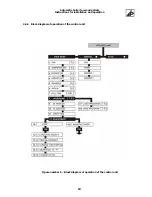
 

Menu user 

See figure number 6. 


Menu manufacturer 

The access in menu is protected by PIN code. 

Further functions of the control unit 

The control unit enables to control the automatic boiler for wood pellets with high level of comfort and 

with a wide variety to adjust the optimum operating mode. See below some other functions of the control 

unit: 

1)    Programmes (heating profiles - Menu 8) make it possible for the user to store 1 - 5  
  

different adjustments of the boiler's operating modes in memory. This may be  


advantageously used, for example, for different kinds of fuel or to adjust the required  


power output. If a change is required, it is sufficient to read the required adjustment from  


memory and to put the boiler in automatic operation. 

2)    Electric moderate heating (Menu 9). Applies to 

KP xxE

, i.e. if the boiler is equipped with electric 

heating coils (in course of production upon  the customer's wish or additionally), the user may allow 

or inhibit electric moderate heating. If the electric moderate heating is allowed, electric heating coils 
will be turned on when the temperature of the heating water drops under 8

°

C; the electric moderate 

heating will be turned off when the temperature of the heating water exceeds 12

°

C. The circulation 

pump is in operation.  Electric moderate heating can be used for moderate heating of buildings 

which are not occupied permanently or to protect the heating system against freezing in time of 
absence.  

3)    Ignition with electric resistance coil - see chapter 6.5. 
4)    Adjustment of some parameters of the boiler by user under simultaneous protection with  


the PIN code seems to be advantageous, if the boiler is placed in rooms with possible  


access of unauthorized persons. This prevents from undesirable interventions in some  


functions of the boiler.  

     5)    Control of cascade connection of 1 - 4 boilers. The function is adjusted by the service  

           engineer in course of putting into operation. 

6)    Protection of feeders with pulse sensors will stop the operation of the control unit, if the  

  expected number of pulses does not come to the input of the control unit. Feeders may be   

  blocked, for example, if improper fuel is used or if a foreign object gets in the transport  

  routes. Operator is notified of this situation with a script " BLOCKED FEEDER x " on the display unit.      
  It is protection of motors against damage and also a fire safety element (if only the feeder 2 gets  

  blocked, this might result in filling the whole transport route with fuel and the fuel might burn  

  through into the bin).  


17

Содержание KP 10

Страница 1: ......

Страница 2: ...uct was with the same responsibility and we are looking forward that the product will provide you with good service Pay attention please to these OPERATING INSTRUCTIONS for correct treatment of this product which is a condition of long service life of this product and thus also your full satisfaction we would like to focus your attention mainly on the following chapters number 1 Important notices ...

Страница 3: ... 5 2 SAFE DISTANCE FROM COMBUSTIBLE MATERIAL 22 5 3 LEGISLATION IN FORCE 22 5 3 1 Heating system and boiler 23 5 3 2 Venting 23 5 3 3 Fire regulations 23 5 3 4 Electrical 23 5 3 5 Noise control 23 5 4 STORAGE OF FUEL 24 5 5 BOILER ROOM VENTILATION 24 6 PUTTING THE PRODUCTS INTO OPERATION 24 6 1 CONNECTION TO THE SYSTEM 24 6 2 INSTALLATION OF THE CERAMIC CATALYTIC REFLECTOR 25 6 3 INSTALLATION OF T...

Страница 4: ... 24 Fig n 12 Parts of the ceramic grate 25 Fig n 13 Ceramic shield 25 Fig n 14 Recommended wiring diagram of boiler 38 Fig n 15 Recommended wiring diagram of boiler 39 Fig n 16 Recommended wiring diagram of boiler cascading wiring 40 Fig n 17 Examples of fuel bins placement of products and requirement on dimensions 41 Fig n 18 Wiring option for supply 3 PE N 50 Hz 400 230 V TN CS 42 Fig n 19 Wirin...

Страница 5: ...s of combustion or to prevent any sparks flying out from the boiler from being the cause of any accident Open the door slowly in order to get the combustion chamber aerated towards the chimney This procedure has to be adhered to when the ash is being removed from the ash pan s space 8 Having the heating season been finished clean the boiler thoroughly as per the chapter 7 Maintenance Products of c...

Страница 6: ...e reduction in manual operation and high operating reliability The structure and software package makes it possible to ensure priority heating of hot service water without any need for other control elements The burner system used with two independent drives and with a system of ceramic catalytic reflector ensures perfect SMOKELESS FUEL COMBUSTION which supports high thermal efficiency of the prod...

Страница 7: ...1E KP 21 21E Weight complete boiler kg 210 270 490 255 335 Water content l 55 70 105 55 70 Fume duct diameter mm 130 150 160 130 150 Connections heating and return water Js G 1 1 2 Heating surface m2 1 8 2 1 2 4 1 8 2 1 Dimensions mm 360x1065x1420 497x1065x1420 745x1285x1630 477x 980x1435 614x980x1435 Working overpressure of water bar up to 2 5 Required draught mbar 0 1 0 2 Recom operating temp of...

Страница 8: ...iciently at individual levels of power output which is moreover assisted by a newly developed system of turbulator of combustion products The exchanger is shaped in such a way so that the exhaust pipes of combustion products can be cleaned individually and efficiently The boiler body is fitted with the following 1 piece of door which makes it possible to ignite the fuel to control burning in cours...

Страница 9: ...ic boiler for wood pellets Instructions for installation and operation Diagram of the products and description of the main parts Figure number 1 Diagram of the product including description of the main parts 8 ...

Страница 10: ...is designed as a compact unit Electric protection IP 65 enables safe and reliable operation of the equipment under hard operating and climatic conditions of boiler rooms Technical data of the CONTROL UNIT Dimensions mm 195 x 215 x 135 Weight kg 3 5 Supply voltage 230 V AC 10 50 Hz 2 Hz Power input own power input max 25 VA Indication LCD display unit to communicate with the operator three point se...

Страница 11: ... elements motors of feeders fan circulation pump etc The connector X2 connects the operating boiler s thermometer emergency thermostat indoor thermostat and other low voltage inputs The connector X3 forms the null bridge for mutual interconnection of shielding conductors PEN Dimensions of the connectors are different and they are provided with mechanical keys against mix up The system also enables...

Страница 12: ...Automatic boiler for wood pellets Instructions for installation and operation 4 2 2 Block diagram of the control unit Figure number 4 Block diagram of the control unit 11 ...

Страница 13: ...lit up when the corresponding equipment is in operation Individual keys control the following devices activities AUTO MANUAL selection between AUTOMATIC and MANUALLY operational mode FAN turns the operation of the fan on and off PUMP turns the operation of the pump on and off FEEDER 1 turns the operation of the 1st fuel feeder on and off in the fuel bin FEEDER 2 turns the operation of the 2nd fuel...

Страница 14: ...Automatic boiler for wood pellets Instructions for installation and operation 4 2 4 Block diagram of operation of the control unit Figure number 6 Block diagram of operation of the control unit 13 ...

Страница 15: ...ng operation of the fan by means of the cursor arrows cursor arrows within the range of 30 100 where increases the quantity of air in steps of 10 reduces the quantity of air in steps of 10 reduces the quantity of air in steps of 1 increases the quantity of air in steps of 1 The manual mode can be left for the automatic mode by depressing the key AUTO MANUAL again b Example of manual control of the...

Страница 16: ...nit for approximately 20 seconds in idle condition it will return back to the MANUAL mode automatically MENU 2 TEMPERATURE of the output water Menu 2 temperature will appear on the display unit after a short notification MAIN MENU and after adjustment to this menu with the key Having the key been depressed a part of the description on the display unit will start blinking If we wish to change the t...

Страница 17: ... reference room of the heated building has exceeded the temperature selected on the indoor thermostat The range of the attenuation period is selectable within the interval of 10 90 min The control unit will do the following at the moment of transition to the attenuation mode light up the indicating lamp FALL display the script FALL on the display unit stop the fuel feeding cycle the fan will be ru...

Страница 18: ...wish or additionally the user may allow or inhibit electric moderate heating If the electric moderate heating is allowed electric heating coils will be turned on when the temperature of the heating water drops under 8 C the electric moderate heating will be turned off when the temperature of the heating water exceeds 12 C The circulation pump is in operation Electric moderate heating can be used f...

Страница 19: ... route spiral chute feeder number 2 including drive an extension piece to install a flexible hose and an extension piece to install a fan A flexible hose made from non flammable material Combustion fan Two electric resistance coils for automatic ignition special equipment Body of the burner is a box type weldment made from highly alloyed material with the bottom oblique input of fuel The fuel is t...

Страница 20: ...sition of the feeder is more perpendicular dosing of fuel is not precise The feeder has its own drive which is controlled by the control unit The feeder is supplied in a standard length equal to 140 cm The feeder 1 consists of the following parts body of the feeder with flanges spiral chute feeder 1 with an electric motor with a gearbox flexible hose to feeder 2 pulse sensor of feeders 4 6 JACKETI...

Страница 21: ... 4 4 5 and 6 kW Circulation pump Digital indoor thermostat Tank to heat service water 100 l 125 l 160 l 200 l Tank with two heating coils to heat service water 200l 250l figure number 7 Storage tanks 500 l 750 l 1000 l Fuel bin Optional accessories are not included in the price of the boiler NTRR 200 NTR 100 Figure number 7 Tank to heat service water Figure number 8 Digital indoor thermostat with ...

Страница 22: ...r including the bin can be placed on If the boiler is installed outside a sub basement boiler room concrete floor it has to stand on a floor made from non flammable material and has to overlap the top view dimension of the equipment being installed by at least 10 cm The necessary height over the boiler to the ceiling of the boiler room is approximately 450 mm cleaning 5 2 SAFE DISTANCE FROM COMBUS...

Страница 23: ...ation of chimneys and fume ducts as well as connection of fuel appliances are governed by the following standard ČSN 73 42 10 Recommended draught of chimney has to be within the range specified by the manufacturer see figure number 9 in connection with the installed power output of the boiler Figure number 9 Recommended draught of the chimney Chimney systems resistant to humidity in which condensa...

Страница 24: ...ents They may be filled without any limits up to their total volume Large volume bins have to meet corresponding fire and safety regulations The supplier is obliged to work out working regulations and instructions for operation and maintenance of large volume bins 5 5 BOILER ROOM VENTILATION Permanent ventilation of the boiler within approximately 75 m3 x hour 1 of fresh air has to be ensured if a...

Страница 25: ...nts which might jeopardize failure free operation of pumps have to be thoroughly rinsed before the system is finally filled with water 6 2 INSTALLATION OF THE CERAMIC CATALYTIC REFLECTOR The ceramic catalytic reflector is manufactured from highly heat resistant material 1500 C It has two functions directs the flow of combustion products through the boiler body assists very efficiently to burn out ...

Страница 26: ...oducts through the exchanger b This grate is installed into the boiler in such a way that individual parts the left part the right part are passed through the middle open part of settling bars and shifted tightly to the wall of the furnace KP 10 KP 11 As regards KP 20 KP 21 we continue in such a way that we will install the middle part of the grate which has the shape of the letter X KP 50 has the...

Страница 27: ...d FEEDER 2 3 Now perform the ignition as such which can be done in several ways a Use classic way of paper and wood chips which will be gradually placed on pellets in the furnace and set on fire b Use the solid firelighter PEPO or ecological firelighter made from excelsior type Jőtul which will be set on fire and placed on the pellets in the furnace c Also a hot air gun may be used to ignite the s...

Страница 28: ...e has been selected when electrical ignition is allowed the following option may be chosen from the menu 10 El ignition with the cursor arrows after the key ENTER has been depressed START This mode is used when the boiler is put into operation for the first time Note If the boiler is equipped for electrical ignition and the electrical ignition is allowed by the programme the state FALL and the tim...

Страница 29: ...electric moderate heating is a substitute operating mode frost blanket measure which makes it possible for the user to apply moderate heating to the whole heating system for example if the user is absent for a long time if there is any failure on the boiler or in case of lack of fuel If the boiler is equipped with electric heating coils the programme of the control unit will ensure that if the hea...

Страница 30: ... totally modern and WOOD PELLETS with clearly guaranteed quality values are exclusively used as fuel the maintenance attendance of the product is very simply during operation 7 1 ATTENDANCE 1 The level of fuel in the bin has always to be kept to be at least 10 cm over the functional transport part of the ribbon flight Irregular dosing may take place in case of further variation reduction of the fu...

Страница 31: ...vidual parts of the ceramic extension grate clean the walls of the boiler including draughts of combustion products clean the surface of the burner Assumed interval 1x a month or after spent fuel cca 1000 kg Note Proceed in reverse order in installation of the removed parts Be careful to place individual parts correctly which is necessary in relation to correct operation of the equipment Therefore...

Страница 32: ...e pulling forward remove all parts of the ceramic extension grate first pull out the middle parts KP 20 KP 21 KP 50 and then both lateral parts KP 10 KP 11 Lift the parts always perpendicularly up then turn them 90 along the longitudinal axis and lower down through the opening in the placement bars which is approximately in the centre of the boiler Now remove all sediments of ash from all ceramic ...

Страница 33: ...ion grate can be precisely placed on them back 6 Back installation of all parts should be done in reverse order Ensure mainly the following in course of this activity Electric resistance coils have to be placed in such a way so that their heating parts are at least 5 mm from the wall of the burner Maximum tightness has to be ensured between the flange of spirals and the wall of the burner The flan...

Страница 34: ...ion on conditions FALL STOP TEMP report on exceeding of emergency temperature the red indicating lamp ALARM lights fault message another proceed in according to par 8 1 STOP STATE the operation of the boiler is stopped by reason that the temperature rise hasn t been reached fault message another proceed in according to par 8 2 BLOCKED FEEDER 1 report on blocked feeder 1 fault message another proce...

Страница 35: ...TEMPERATURE DROP If the boiler does not reach the expected temperature of 30 C within 10 minutes after ignition the control unit will assess this situation as abnormal and operation of the boiler will be stopped Reasons may be low quality fuel lack of fuel impassable transport routes etc This situation is indicated by the following script on the display unit STOP STATE Useless idle operation of th...

Страница 36: ...ler every electricity supply interruption triggers the electric ignition routine and thus further automatic operation is started boiler WITHOUT electric ignition automatic operation mode State of fuel burning in the boiler has to be checked after electricity supply interruption Manual ignition has to be performed see chapter 6 6 if the fire has been extinguished 9 DISPOSAL OF PRODUCT AFTER THE END...

Страница 37: ...llation of the boiler and putting it into operation only by an authorized servicing organization which has the manufacturer s accreditation and the user is also obliged to send the letter of guarantee number 1 to the manufacturer s address immediately after the product has been put into operation 2 The boiler has to be operated only within these Instructions for operation and only prescribed fuel ...

Страница 38: ...ctions for installation and operation RECORDS OF PERFORMED REPAIRS guarantee and after guarantee repairs Attachment to the letter of guarantee for user Date Intervention performed Stamp and signature of contractual service User s signature 37 ...

Страница 39: ...Automatic boiler for wood pellets Instructions for installation and operation Figure number 14 Recommended wiring diagram of boiler 38 ...

Страница 40: ...Automatic boiler for wood pellets Instructions for installation and operation Figure number 15 Recommended wiring diagram of boiler 39 ...

Страница 41: ...Automatic boiler for wood pellets Instructions for installation and operation Figure number 16 Recommended wiring diagram of boiler cascading wiring 40 ...

Страница 42: ...Automatic boiler for wood pellets Instructions for installation and operation Figure number 17 Examples of fuel bins placement of products and requirement on dimensions 41 ...

Страница 43: ...Automatic boiler for wood pellets Instructions for installation and operation Figure number 18 Wiring option for supply 3 PE N 50 Hz 400 230 V TN C S 42 ...

Страница 44: ...Automatic boiler for wood pellets Instructions for installation and operation 43 Figure number 19 Wiring option for supply 3 NPE 50 Hz 400 230 V TN S ...

Страница 45: ...Automatic boiler for wood pellets Instructions for installation and operation 44 Figure number 20 Schema wiring el ignition el heating Figure number 21 Schema wiring electromotive control 4 way valve ...

Страница 46: ... wood pellets Instructions for installation and operation 45 Figure number 22 Wiring room thermostat with weekly programme and independent drive heating HUW Figure number 23 Working principle The Boiler in mode modulation ...

Страница 47: ...Automatic boiler for wood pellets Instructions for installation and operation 46 Figure number 24 Directory information consuption wood pellets for boiler family KP ...

Страница 48: ...me 45 min Programs kW Feeder 1 ON Feeder 1 OFF Advance Feeder2 Run in Feeder2 Fan Fall time Temperature P 1 7 5 5 90 1 5 30 45 80 P 2 13 5 5 45 1 5 45 45 80 P 3 20 0 5 29 1 5 53 45 80 P 4 22 5 5 25 1 5 64 45 80 P 5 25 0 5 22 1 5 75 45 80 P 6 22 5 5 25 1 5 64 45 80 9 El Heating No 10 El Ignition No 1 Fan 75 2 Temperature 80 C 3 Feeder 1 ON 10 s 4 Feeder 1 OFF 20 s 5 Advance Feeder 2 1 s 6 Run in Fe...

Страница 49: ...l Heating No 10 El Ignition No 1 Fan 47 2 Temperature 80 C 3 Feeder 1 ON 9 s 4 Feeder 1 OFF 22 s 5 Advance Feeder 2 1 s 6 Run in Feeder 2 3 s 7 Fall time 45 min Programs kW Feeder 1 ON Feeder 1 OFF Advance Feeder2 Run in Feeder2 Fan Fall time Temperature P 1 5 1 9 85 1 3 30 45 80 P 2 9 4 9 43 1 3 36 45 80 P 3 13 6 9 27 1 3 43 45 80 P 4 15 3 9 22 1 3 47 45 80 P 5 17 0 9 20 1 3 51 45 80 P 6 15 3 9 2...

Страница 50: ...ets burnt out the control unit will evaluate this fact shortly and the boiler gets stopped The combustion chamber and the burner thus do not get filled with unburnt fuel Electric equipment of the boiler has been expanded with Connector CANON 25 located on the subpanel on the rear side of the boiler see the figure number Ti001 1 Interconnection of the boiler with the control unit see the figure num...

Страница 51: ...mbustion products is higher than the adjusted t value the boiler resumes its operation If the temperature value is lower than the t value the boiler will get to the state STOP ignite fail Boiler without automatic ignition The t value is always evaluated after the boiler gets to the mode of AUTO AUTOx or BOILER from the STANDBY mode at the pre programmed moment in time No evaluation takes place und...

Страница 52: ...ines are put out of operation turned off Note Changes in adjustment of values are accepted by the control unit after the RESET of the equipment the control unit has to be truned off and on Software change in circuitry from the serial number 291 2006 on Use in case of products family KPxx equipped with combustion products thermometer Figure number Ti001 3 ...

Страница 53: ...transport route is increased by installation of thermostat placed in the burner where the fuel enters the burner It is a provision exceeding the requirements of the standard ČSN EN 303 5 and increases safety The following has been added to the electric equipment of the boiler Burner thermostat Interconnection of both emergency thermostats in series connection see figure number 4 page 11 Indicator ...

Страница 54: ...and feeder 2 may not contain any fuel The burner and mainly its air nozzles should be checked whether they are clean The secondary ceramic grate should be checked whether it is clean The boiler and routes of its combustion products should be checked whether they are clean The chimney should be checked whether it is clean as well as its draught If the parts have been cleaned and they are in order t...

Страница 55: ...and the flange of the gear box has to be limited with a corresponding washer in order to prevent from any deformation of the disc when the screw is tightened Two distance columns OK 10x20 shall be screwed on the face of the gear box on which the cover of the sensor with electronics will be fastened by means if 2 screws M 6x10 with washers 6 2 The sensor is equipped with a non detachable cable with...

Страница 56: ...bution box mounted on the front side of the daily weekly fuel bin with an independent electric power supply and electric connection to the drive of the feeding screw P 0 Figure number Ti004 1 Description of operation The automatic system controls replenishment of daily weekly fuel bin from the seasonal fuel storage room depending on the time adjustment and emptying of the daily weekly fuel bin It ...

Страница 57: ... Figure number Ti005 1 The microwave aerial is equipped with a magnet for easy fastening Description of operation The software package of the control unit is enlarged with the programme routines to receive and emit short text messages A set of defined commands which ensure simple control of the boiler STATUS this command will be responded by the control unit with information on the momentary opera...

Страница 58: ...trol unit SW modification In the menu 12 Setup 12 1 User PIN 1 the following menu has been added 12 1 5 GSM modem Enabled the selected command will be confirmed by the key ENTER the control unit will confirm acceptance of the command by short blink and by the following notification Enabled and resumes the work with the adjusted telephone numbers processes incoming text messages and send informatio...

Страница 59: ...llowing command ESC 3 the following menu is added 12 1 7 Mobile number 2 everything as in the menu 12 1 6 Mobile number 1 apples to the function adjustment and control the only limitation is that no failure messages are sent to this number 4 the following menu is added 12 1 8 Credit number if a SIM card with credit charging is used this menu may be used to enter a number where a corresponding oper...

Отзывы: