


NOTE:
Read the entire instruction manual before starting the installation. These instructions must be affixed on or adjacent to the boiler.
This symbol
→
indicates a change since the last issue.
ama
ASME
®
A88177
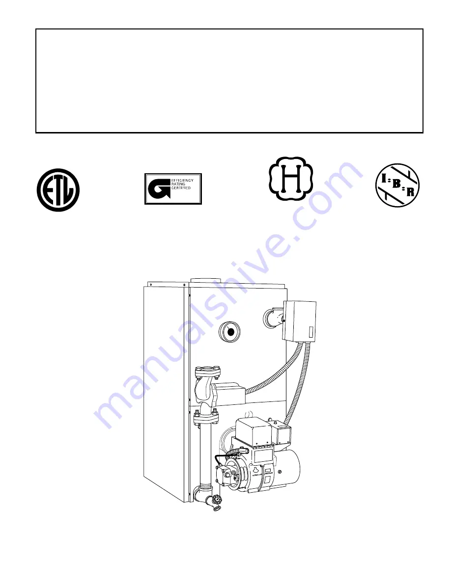
MODEL BW4/BW5
Installation, Start-Up, and Operating Instructions
BW4
BW5
Oil-Fired
Cast Iron Hot Water Boilers
Sizes 74,000 through 239,000
Series A
Form:
IM-BW4A-03
Cancels:
IM-BW4A-02
Printed in U.S.A.
5-98
Catalog No.
63BW-4A0


