


Catalog No.: 3400.52D
Effective:
04-01-03
Replaces:
02-15-03
FOR YOUR SAFETY
Do not store or use gasoline or other flammable vapors and liquids or other combustible materi-
als in the vicinity of this or any other appliance. To do so may result in an explosion or fire.
WARNING:
Improper installation, adjustment, alteration, service or maintenance can cause prop-
erty damage, personal injury or loss of life. Refer to the user’s information manual provided with
this boiler. Installation and service must be performed by a qualified installer, service agency or
the gas supplier.
FOR YOUR SAFETY
WHAT TO DO IF YOU SMELL GAS:
·
Do not try to light any appliance.
·
Do not touch any electrical switch; do not use any phone in your building.
·
Immediately call your gas supplier from a neighbor’s phone. Follow the gas supplier’s
instructions.
·
If you cannot reach your gas supplier, call the fire department.
This manual should be maintained in legible condition
and kept adjacent to the boiler or kept in a safe place
for future reference.
P/N 241079
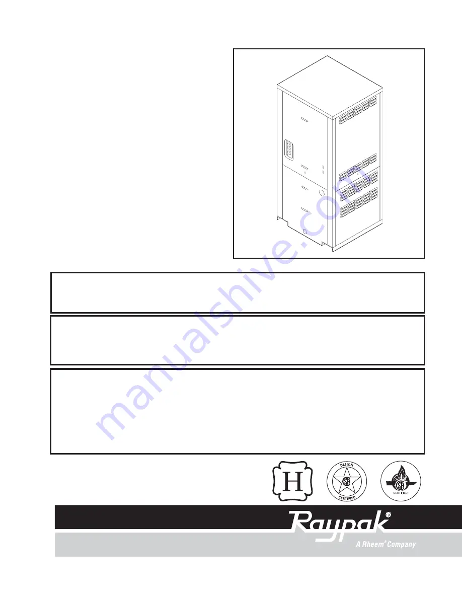
OPERATING AND
INSTALLATION
INSTRUCTIONS
Model 751, 1001, 1501
TYPE H, WH, P
A
DVANCED
D
ESIGN
B
OILER
Summary of Contents for 1001
Page 6: ...6 FigureA 1 ADVANCED DESIGN BOILER COMPONENT LOCATIONS...
Page 15: ...Figure E 2b SINGLE BOILER PRIMARY SECONDARY PIPING WITH CHX 15 Figure E 3a DUAL BOILER PIPING...
Page 21: ...Figure G 3a DOUBLE BOILER POOL APPLICATION 21...
Page 53: ...53 Figure L 2 WIRINGDIAGRAM...
Page 58: ...58 Figure O 1 COMPONENTAND PRESSURE TAP LOCATIONS Blower T fitting detail...
Page 68: ...68...
Page 69: ...69...
Page 70: ...70...
Page 71: ...71...
Page 72: ...72...
Page 73: ......


