background image


PN3362421 


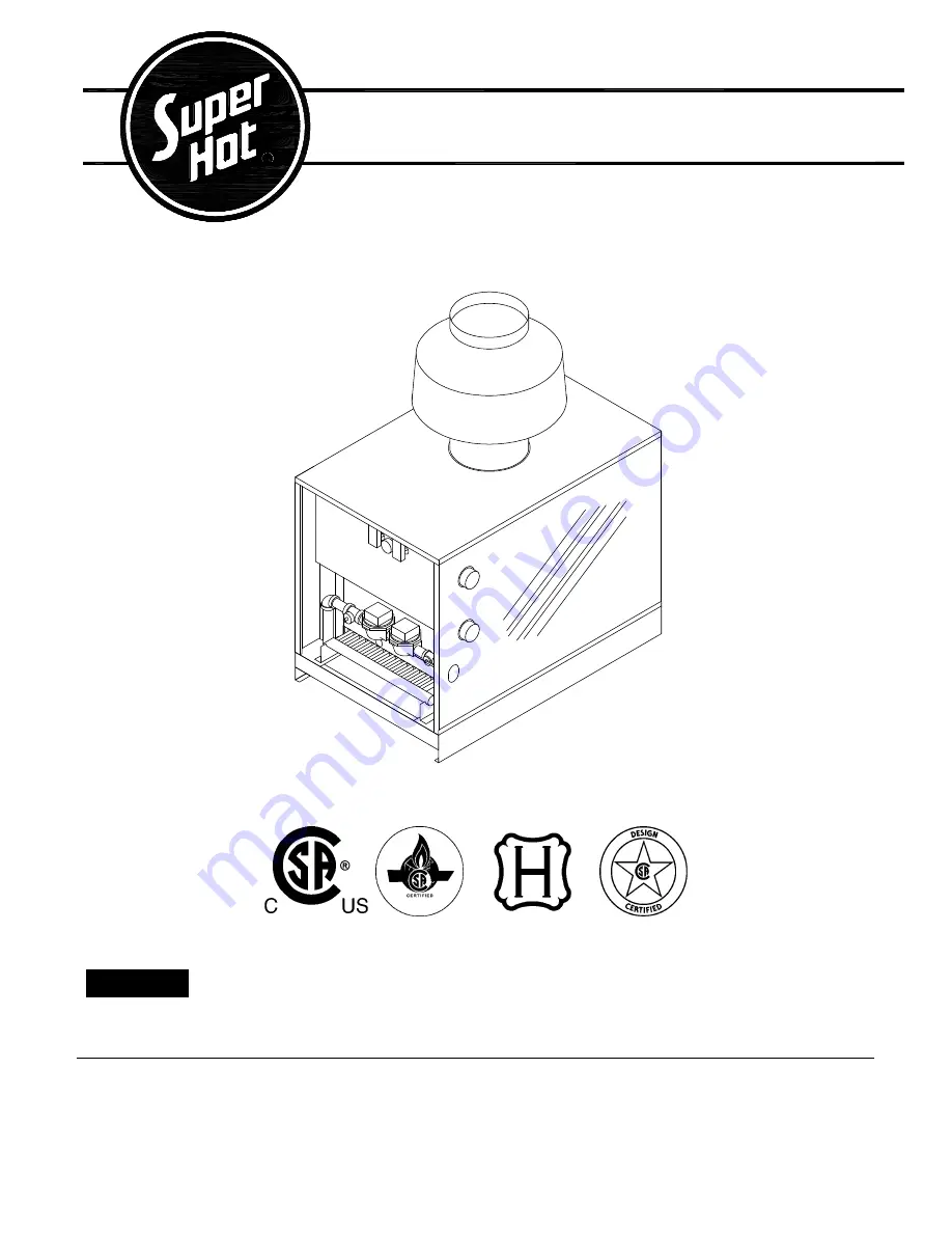
AAA SERIES GAS BOILERS


INSTALLATION AND SERVICE MANUAL


FOR MODELS AAA-480 TO AAA-3000 

Featuring the BTC SERIES Controller on 1 & 2 stage models 

See rear cover for Index


Manufactured by 

Allied Engineering Company


Division of E-Z-Rect Manufacturing Ltd. 

Manufacturers of Gas and Electric Boilers, Stainless Steel Tanks, Heat Exchangers and Electric Boosters 

94 Riverside Drive, North Vancouver, B.C. V7H 2M6 

 Telephone (604) 929-1214 

 www.alliedboilers.com 

Branches: Calgary 

 Edmonton 

 Toronto


Improper installation, adjustment, alteration, service or maintenance can cause property 
damage,  injury,  or  loss  of  life

.

  Please  carefully  read  this  manual.  For  assistance  or 

additional information, consult a qualified installer, service agency or the gas supplier. 


WARNING 

Summary of Contents for AAA-3000 series

Page 1: ...f Gas and Electric Boilers Stainless Steel Tanks Heat Exchangers and Electric Boosters 94 Riverside Drive North Vancouver B C V7H 2M6 Telephone 604 929 1214 www alliedboilers com Branches Calgary Edmonton Toronto Improper installation adjustment alteration service or maintenance can cause property damage injury or loss of life Please carefully read this manual For assistance or additional informat...

Page 2: ...0 10 5 26 7 16 40 6 76 0 193 0 19 5 49 5 1 1 4 11 53 43 6 990 450 AAA1200 1200 352 1020 299 30 5 42 106 7 10 5 26 7 16 40 6 76 0 193 0 21 0 53 3 1 1 4 12 73 48 2 1050 477 AAA1320 1320 387 1122 329 33 5 45 114 3 10 5 26 7 18 45 7 77 3 196 3 22 5 57 2 1 1 4 13 92 52 7 1140 518 AAA1440 1440 422 1224 359 36 6 48 121 9 10 5 26 7 18 45 7 77 3 196 3 24 0 61 0 1 1 4 15 12 57 2 1205 548 AAA1560 1560 457 13...

Page 3: ... Number U S GPM P D FT U S GPM P D FT AAA480 41 0 3 0 27 3 1 35 AAA600 51 2 3 0 34 1 1 35 AAA720 61 4 3 0 41 0 1 35 AAA840 71 7 3 0 47 8 1 35 AAA960 81 9 3 0 54 6 1 35 AAA1080 92 2 3 0 61 4 1 35 AAA1200 102 4 3 0 68 3 1 35 AAA1320 112 7 3 0 75 1 1 35 AAA1440 122 9 3 0 81 9 1 35 AAA1560 133 1 3 0 88 8 1 35 AAA1680 143 4 3 0 95 6 1 35 AAA1800 153 6 3 3 102 4 1 35 AAA1920 163 9 3 3 109 2 1 5 AAA2040 ...

Page 4: ...operty damage personal injury or loss of life A BEFORE LIGHTING smell all around the boiler area for gas Be sure to smell next to the floor because some gas is heavier than air and will settle on the floor WHAT TO DO IF YOU SMELL GAS Do not try to light any appliance Do not touch any electrical switch do not use any phone in your building Immediately call your gas supplier from a neighbor s phone ...

Page 5: ...ld lockout and all functions are off 5 To take the control system out of lockout either press the reset button or interrupt power to the boiler depending on the boiler controller Some controllers will retry ignition automatically after 5 minutes lockout Start System 1 Turn on the main and pilot manual gas shut off valves 2 Set thermostat above room temperature and turn on all electrical power to t...

Page 6: ...icable local codes In the United States of America the installation must conform to the requirements of the authority having jurisdiction or in the absence of such requirements to the National Fuel Gas Code ANSI Z223 1 current edition All electrical wiring must be in accordance with the National Electrical Code ANSI NFPA 70 current edition and applicable local codes Where required by the authority...

Page 7: ...nt air supply MUST be provided to this boiler Air openings to the boiler room provide the air for combustion flue gas dilution and ventilation and are always required regardless whether the air is taken from inside or outside The air opening size and location as well as other air supply and venting considerations must conform to Section 2 2 The boiler room must never be under a negative pressure A...

Page 8: ... of snow and other debris at all times To prevent discoloration and degradation of building materials by flue gases and flue gas condensation ensure that the vent terminal is installed clear of nearby obstacles In all cases installation shall be in accordance with code Maintain a minimum clearance of 4 feet 1 22 m horizontally and in no case above or below unless a 4 foot 1 22 m clearance is maint...

Page 9: ...maintained at a neutral pH e g Fernox Alphi 11 or equivalent Follow the supplier s instructions for proper use and maintenance Do not use automotive antifreeze Some types of chemical additives can cause problems such as accelerated corrosion and result in premature failure of the boiler heat exchanger and or system components especially when not properly used or maintained Corrosion is a preventab...

Page 10: ...boiler may be connected to more than one electrical circuit Turn off all electric power supply circuits at the electrical service panel or supply source Failure to do so may result in severe personal injury or death All electrical wiring must conform to the requirements in Section 2 2 Run a separate circuit from the electrical service panel through a fused disconnect switch to the boiler This boil...

Page 11: ...AAA Series Gas Boiler Installation and Service Manual 11 Field wiring to terminal block TB4 Figure 1 Field wiring to terminal block TB4 ...

Page 12: ...nstalled on an exterior wall typically facing North and above the snow line It should be shielded from effects of heat or cold to prevent false outdoor temperature readings Avoid direct sunlight exhaust fans appliance vents and excessive moisture SD CM Supply DHW Sensor Optional for Modes 2 3 and 5 only Connect a Supply or DHW Sensor 071 to terminals SD and CM common The Supply DHW sensor is inser...

Page 13: ... Boiler Stage outputs from 15 STG1 and 17 STG2 terminals are 24 Vac 60 Hz when factory wired Alarm output from 23 ALARM terminal is 24 Vac 60 Hz 0 45 A maximum when factory wired Alarm is wired to terminal block TB4 terminals AL AL Signal Inputs Do not apply external power The following signal inputs are located on terminal block TB4 HT R Room thermostat or zone valve end switch 24Vac switching in...

Page 14: ... press and hold simultaneously all three buttons for 1 second The display then advances to the Adjust menu and the ADJUST segment is turned on in the display The display will automatically revert back to the View menu after 20 seconds of keypad inactivity Once in a menu there will be a group of items that can be viewed within that menu Item The abbreviated name of the selected item will be display...

Page 15: ...3 parallel dedicated DHW generation only Mode 4 parallel outdoor reset with optional DHW override Mode 5 primary secondary outdoor reset with optional DHW override BOIL TARGET 180 F Minimum boiler target temperature during reset override setpoint or DHW operation TANK TARGET 140 F Sets the DHW storage tank s temperature Used in Mode 3 only TANK DIFF 5 F Sets the differential for the DHW storage ta...

Page 16: ...de boiler pump control and operates stage 1 and pump when a heat demand is present The stage 1 terminals on the external boiler control must be connected to the heat demand terminals HT R of terminal block TB4 on the boiler Next the 5 6 jumper wire of terminal block TB1 on the boiler must be removed and the stage 2 terminals on the external boiler control connected to 6 and 24Vac R See wiring diag...

Page 17: ...relay causes the following actions 1 Power for the boiler pump Pump1 is broken Pump1 does not operate 2 Power for the DHW pump Pump2 is made Pump2 operates 3 Setpoint DHW Demand creates a boiler target based on the higher requirement of the outdoor reset and reset override setting Figure 5 Wiring diagram illustrating use of an External Relay to control pump operation 2 S 1 S 1 T 1 T 1 A 1 Pump 2 P...

Page 18: ...ING The following instructions are intended as a guide for qualified persons Before lighting the boiler the pre startup instructions of Section 4 1 MUST be performed If you do not follow these instructions exactly a fire or explosion may result causing property damage personal injury or loss of life Intermittent pilot This boiler does not have a continuous pilot flame It is equipped with an igniti...

Page 19: ...controller will regulate the boiler water temperature using the two stages The number of stages that switch on is based on the heating demand and user settings Check main and pilot burners and adjust pilot if necessary as described in Section 4 3 After all room thermostats are satisfied the controller de energizes the two stages in sequence 8 Assure that all other gas appliances are turned off inc...

Page 20: ...sage of products of combustion to the flue Under typically operating conditions the flame should have a distinct bright blue inner cone and a blue orange outer cone If any of the above problems are observed or the burner system does not operate properly immediately take corrective measures 4 4 AQUASTAT ADJUSTMENT The factory mounted aquastat controls main burner firing by sensing outlet water temp...

Page 21: ...RNING Exceeding the allowable input rate can produce dangerous concentrations of carbon monoxide and cause the boiler to overheat resulting in severe personal injury death or substantial property damage Carbon monoxide is a lethal colorless and odorless gas Input Rate Test Consult gas company to determine the heating value of the gas supplied in Btu per cubic feet Operate boiler for 15 minutes sta...

Page 22: ...hood IMMEDIATELY shutdown the boiler and make proper adjustments or repairs 4 8 CHECK OF CONTROLS After the unit has been operated for awhile lower the aquastat setting below the setpoint and burner should shut off Rotate the aquastat higher than setpoint and the main burner should ignite Return the aquastat to its original setpoint and make sure boiler cycles normally Repeat this type of check on...

Page 23: ... on the boiler rating plate Clocked BTU H Input Rate ______________ 4 6 Set BTC Series Controller mode of operation and other applicable parameters See BTC Series Controller Manual for detailed information 3 1 3 2 3 3 3 4 Perform check of temperature controls aquastat high limit aquastat and thermostat 4 4 4 8 Test any other controls as specified by the manufacturer Visually inspect main burners a...

Page 24: ...the heating season for continued safe operation Note that some operating conditions may require more frequent inspections The qualified service technician or gas supplier s service person should follow the Service Checklist The Service Checklist must only be used by a qualified service technician or gas supplier s service person Verify proper operation after servicing 5 2 CLEANING PROCEDURE 1 Shut...

Page 25: ...artially restrict free passage of products of combustion to the flue 4 3 Check that gas piping is secured Smell for gas leaks around boiler and gas piping connections Gas leaks can also be checked for using a soap solution do not use an open flame to check for leaks Note Propane is heavier than air and pools in a low area in the event of a leak 4 9 Inspect for leaks in the water piping and at wate...

Page 26: ... levels of nuisance dust and poses increased carcinogenic risk Follow the precautionary measures below before attempting service or access PRECAUTIONARY MEASURES Avoid breathing fibers and contact with skin and eyes Use a National Institute for Occupational Safety and Health NIOSH approved dust mist respirator Wear long sleeved loose fitting clothing gloves and eye protection Wash work clothes sep...

Page 27: ...ed for replacement under standard company warranties must be properly tagged with Return Goods Authorization Form R G A completely filled in with the boiler serial number model number etc and shipped to the Company freight prepaid If determined defective by the Company and within warranty the part will be returned in kind or equal substitution freight collect Credit will not be issued Refer to Fig...

Page 28: ...AAA Series Gas Boiler Installation and Service Manual 28 ...

Page 29: ...AAA Series Gas Boiler Installation and Service Manual 29 Wiring Diagrams Section 7 ...

Page 30: ...AAA Series Gas Boiler Installation and Service Manual 30 ...

Page 31: ...AAA Series Gas Boiler Installation and Service Manual 31 ...

Page 32: ...re closed position Check gas valve and replace if necessary Thermocouple failure Check thermocouple and replace if necessary Faulty wiring Check wiring of aquastats zone valves and thermostats for loose or broken wires and repair Faulty aquastat thermostat or zone valve Check and replace if necessary Boiler will not fire Pilot not lit Relight standing pilot For electronic ignition see Pilot flame ...

Page 33: ...pair if necessary Gas supply pipes not purged of air Purge gas line Low pilot gas pressure Adjust pressure Pilot flame will not light on electronic ignition Dirt or foreign material in pilot Clean Incorrect pilot flame pressure Set pilot pressure to correct pressure Poor connections in wiring to flame sensor Repair wiring Electrodes are damaged Replace electrodes Pilot lights but flame failure aft...

Page 34: ...AAA Series Gas Boiler Installation and Service Manual 34 NOTES Section 9 ...

Page 35: ...AAA Series Gas Boiler Installation and Service Manual 35 NOTES Section 9 ...

Page 36: ...rnal 9 2 10 System Operating Requirements 9 2 11 Pressure Relief Valve 10 2 12 Electrical Wiring 10 2 13 BTC Series Controller Wiring 10 3 BTC Series Controller Information 13 3 1 Controller Information 13 3 2 Controller Display 14 3 3 Controller Operation 16 3 4 Reset Override 16 3 5 Controller Mounting 18 4 Startup Instructions 18 4 1 Pre startup 18 4 2 Startup 18 4 3 Check Burner System 20 4 4 ...

Reviews: