Automatic boiler for wood pellets
Instructions for installation and operation
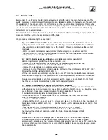
7) Priority heating of hot service water. Excellent properties of this function can fully be
used, if the boiler is connected as per the figure number 15. This function will ensure
heating of hot service water within a minimum time interval. If the boiler sends a request
to heat the hot service water (temperature of water will get reduced and the boiler's
thermostat will switch in), the control unit will:
- stop the circulation pump in the central heating system
- the boiler will start working as per the programme P6 - item 1 (should be adjusted to the
maximum power output)
- the servo actuator will re-route the water from the whole system into the
water heater
- when the temperature of the boiler water is > 60°C, the control unit will turn the boiler's
pump on
- the automatic operation of the boiler will be resumed (original state) after the water has
been heated (the boiler's thermostat will be turned off)
4.3 BURNER FURNACE INCLUDING THE FEEDER 2 WITH INDEPENDENT DRIVE
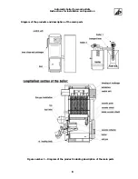
A diagram of the burner furnace is shown as a part of the figure number 1 and the burner furnace
consists of the following parts:
- The body of the burner as such including the built-in transport route (spiral-chute feeder number 2
including drive), an extension piece to install a flexible hose and an extension piece to install a fan.
- A flexible hose made from non-flammable material.
- Combustion fan.
- Two electric resistance coils for automatic ignition (special equipment).
Body of the burner
– is a box-type weldment made from highly alloyed material with the bottom
oblique input of fuel. The fuel is transported by a built-in spiral-chute
feeder 2
driven by an electric
motor with a gearbox.
Assembly of slotted nozzles ensures supply of combustion air in order to reach controlled and
perfect combustion of the supplied fuel during the time when the fuel is in the combustion space of
the burner.
The spent fuel is then shifted through the overflow edge of the combustion space into the ash
pan.
The inside space of the burner's body is connected to the
air fan
the revolutions of which may
be widely regulated (see the paragraph on the control unit) in connection with the required power
output of the boiler or with the fuel type used.
The
flexible hose
to feeder 2 made from non-flammable material interconnects both feeders
and is thus a part of the transport routes for fuel.
The flexible hose has to be installed so that it:
- does not form considerably rippled folds which block smooth movement of the fuel and
must be built-in under an angle min. 70
°
(to horizontal plane).
- its fixation on both tube extension pieces has to be tight.
18
Содержание KP 10
Страница 1: ......

