ENGINE
3.40
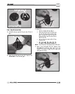
Cam Gear Spring Installation Tool Kit:
(PU--45497)
Tapered Pins:
(PU--45497--1)
Cam Gear Tooth Align Tool:
(PU--45497--2)
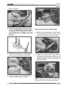
18. Line up the two gears using the timing marks and
the three gear tabs that were referenced earlier.
Push the gears back together, using both hands
and hold securely.
Align Timing Marks
19. Once the gears are pressed together, firmly hold
the gears together with one hand. Carefully
remove the Tapered Pins (
PU--45497--1
) by
pulling them out one at a time with the other hand.
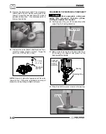
20. After the tapered pins are removed, be sure the
cam gear assembly is held together tightly. Place
the cam gear assembly on a flat surface. Use the
Cam Gear Tooth Alignment Tool (
PU--45497--2
)
(R) to align the teeth of the cam gears, as shown
in the picture.
NOTE:
Install the Cam Gear Alignment Tool
(
PU--45497--2
) into one assembly hole counter
clockwise from the timing mark.
PU--45497--2
NOTE:
For ease of installing the Cam Gear
Alignment Tool (
PU--45497--2
) (R), use a twisting
motion when pushing down on the tool.
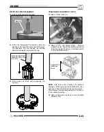
21. To remove the balance shaft gear, the flat side of
the camshaft (P) must face the balance shaft
gear. To rotate the camshaft, use the Cam
Spanner Wrench (
PU--45498
) to rotate the
camshaft so the flat side of the camshaft faces the
balance shaft gear.
PU--45498
P
NOTE:
This Cam Spanner Wrench (
PU--45498
) is
only needed to rotate the camshaft when the entire
valve train is assembled. If the rocker arms are
removed, the cam--shaft can be turned by hand.
22. Remove the bolt and nut from the balance shaft
gear. Try to remove the balance shaft gear. If the
gear does not come off manually, use the
Flywheel Puller (
PN 2871043
) to remove the
Содержание 600 Dragon SP
Страница 1: ...2004 SPORTSMAN 600 700 SERVICE MANUAL PN 9918803 ...
Страница 138: ...BODY STEERING SUSPENSION 5 16 NOTES ...
Страница 210: ...FINAL DRIVE 7 38 NOTES ...
Страница 293: ...ELECTRICAL 10 43 WIRING DIAGRAM HAND AND THUMB WARMERS WINCH HUNTER EDITION ...
Страница 294: ...ELECTRICAL 10 44 NOTES ...
Страница 295: ...ELECTRICAL WIRING DIAGRAM EARLY 2004 SPORTSMAN 600 700 BUILT BEFORE FEB 20 2003 Built Before February 20 2003 ...
Страница 297: ...ELECTRICAL WIRING DIAGRAM LATE 2004 SPORTSMAN 600 700 BUILT AFTER FEB 20 2003 Built After February 20 2003 ...
Страница 298: ...ELECTRICAL WIRING DIAGRAM LATE 2004 SPORTSMAN 600 700 BUILT AFTER FEB 20 2003 Built After February 20 2003 NOTES ...
Страница 299: ...ELECTRICAL WIRING DIAGRAM LATE 2004 SPORTSMAN 600 700 MODELS WITH FUEL GAUGE Models Equipped with Fuel Gauge ...
Страница 300: ...ELECTRICAL WIRING DIAGRAM LATE 2004 SPORTSMAN 600 700 MODELS WITH FUEL GAUGE NOTES ...
Страница 301: ...ELECTRICAL WIRING DIAGRAM 2004 SPORTSMAN 600 700 HUNTER EDT HAND WARM WINCH ...
Страница 307: ...Winch Switch Installation 10 34 Winch Wiring 10 35 Wiring Diagram Hand Thumb Warmer Winch 10 43 ...
Страница 308: ...PN 9918803 Printed in USA ...


