


ELECTRICAL
10.21
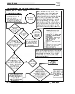
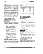
Connect an ammeter in series with the negative
battery cable. Check for current draw with the key off.
If the draw is excessive, loads should be
disconnected from the system one by one until the
draw is eliminated. Check component wiring as well
as the component for partial shorts to ground to
eliminate the draw.
Refer to Illustration 1 on the next page.
--
+
Current Draw Inspection
Key Off
YB30L--B
Ill. 1
Current Draw - Key Off:
Maximum of .01 DCA (10 mA)
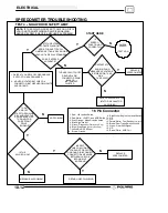
CHARGING SYSTEM “BREAK
EVEN” TEST
CAUTION:
Do not allow the battery cable or
ammeter to become disconnected with the
engine running. Follow the steps below as
outlined to reduce the chance of damage to
electrical components.
WARNING:
Never start the engine with the ammeter
connected in series. Damage to the meter or meter
fuse will result. Do not run test for extended period of
time. Do not run test with high amperage accessories.
The “break even” point of the charging system is the
point at which the alternator overcomes all system
loads (lights, etc.) and begins to charge the battery.
Depending on battery condition and system load, the
break even point may vary slightly. The battery should
be fully charged before performing this test.
1. Connect
a
tachometer
according
to
manufacturer’s instructions.
2. With the negative cable still connected to the
battery, connect one meter lead (set to DC amps)
to the battery post and the other to the negative
battery cable
3. With engine off and the key and kill switch in the
ON position, the ammeter should read negative
amps (battery discharge). Reverse meter leads if
a positive reading is indicated.
4. Shift transmission into neutral and start the
engine.
With the engine running at idle,
disconnect the negative cable from the battery
post without disturbing the meter leads.
Observe
meter readings
5. Increase engine RPM while observing ammeter
and tachometer.
6. Note RPM at which the battery starts to charge
(ammeter indication is positive).
7. With lights and other electrical load off, the “break
even” point should occur at approximately 1500
RPM or lower.
8. Turn the lights on and engage parking brake lock
to keep brake light on.
9. Repeat test, observing ammeter and tachometer.
With lights on, charging should occur at or below
2000 RPM.
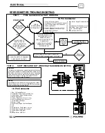
ALTERNATOR OUTPUT TEST
(AC AMP)
This test measures AC amperage from the alternator.
CAUTION:
This test simulates a “full load” on the
alternator at idle. Do not increase idle RPM or perform
this test longer than required to obtain a reading. The
alternator stator windings may overheat. 3--5 seconds
is acceptable. Failure to place red lead in the
fuse--protected “10 Amp” socket will damage the meter.
To Calculate Available Alternator Output
250W
12V
= 20.8 Amps
I
=
P
E
I = Current in Amps
P = Power in Watts
E = Electromotive Force (Volts)
200W
12V
= 16.7 Amps
1. Maximum alternator output will be indicated on the
meter. DO NOT increase engine RPM above idle.
2. Place the red lead on the tester in the 10A jack.
3. Turn the selector dial to the AC amps (A )
position.
4. Connect the meter leads to the Yellow and
Yellow/Red wires leading from the alternator.
5. Start the engine and let it idle. Alternator Current
Output Reading should be a minimum of
7A/AC
at idle
.
Содержание 600 Dragon SP
Страница 1: ...2004 SPORTSMAN 600 700 SERVICE MANUAL PN 9918803 ...
Страница 138: ...BODY STEERING SUSPENSION 5 16 NOTES ...
Страница 210: ...FINAL DRIVE 7 38 NOTES ...
Страница 293: ...ELECTRICAL 10 43 WIRING DIAGRAM HAND AND THUMB WARMERS WINCH HUNTER EDITION ...
Страница 294: ...ELECTRICAL 10 44 NOTES ...
Страница 295: ...ELECTRICAL WIRING DIAGRAM EARLY 2004 SPORTSMAN 600 700 BUILT BEFORE FEB 20 2003 Built Before February 20 2003 ...
Страница 297: ...ELECTRICAL WIRING DIAGRAM LATE 2004 SPORTSMAN 600 700 BUILT AFTER FEB 20 2003 Built After February 20 2003 ...
Страница 298: ...ELECTRICAL WIRING DIAGRAM LATE 2004 SPORTSMAN 600 700 BUILT AFTER FEB 20 2003 Built After February 20 2003 NOTES ...
Страница 299: ...ELECTRICAL WIRING DIAGRAM LATE 2004 SPORTSMAN 600 700 MODELS WITH FUEL GAUGE Models Equipped with Fuel Gauge ...
Страница 300: ...ELECTRICAL WIRING DIAGRAM LATE 2004 SPORTSMAN 600 700 MODELS WITH FUEL GAUGE NOTES ...
Страница 301: ...ELECTRICAL WIRING DIAGRAM 2004 SPORTSMAN 600 700 HUNTER EDT HAND WARM WINCH ...
Страница 307: ...Winch Switch Installation 10 34 Winch Wiring 10 35 Wiring Diagram Hand Thumb Warmer Winch 10 43 ...
Страница 308: ...PN 9918803 Printed in USA ...


