


FINAL DRIVE
7.33
Joint Capacity
50 Grams
Boot Capacity
30 Grams
Joint Capacity
50 Grams
Boot Capacity
50 Grams
INBOARD
100g Total
OUTBOARD
80g Total
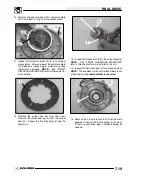
NOTE:
CV Joint Grease Capacity:
CV Joint Grease - 30g (PN 1350046)
50g (PN 1350047)
Outboard joint - 30g if boot is replaced only. Another
50g (80 total) if joint is cleaned.
Inboard joint - 50g if boot is replaced only. Another
50g (100total) if joint is cleaned.
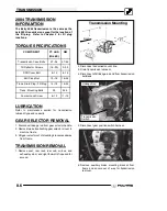
REAR PROPSHAFT
REMOVAL/INSTALL
Transmission
Propshaft
Rear Gearcase
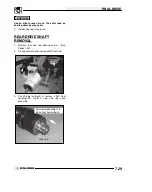
1. Loosen or remove the bolts the bolts that secure
the rear gearcase to the frame. Slide the rear
gearcase back enough to slide the rear propshaft
from the transmission shaft. Remove the rear
drive shaft.
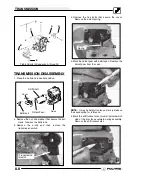
2. To install the rear propshaft:
G
Slide transmission end of propshaft
onto the transmission output shaft
G
Slide the rear gearcase back into
place and align propshaft to rear
gearcase input shaft
G
Tighten the rear gearcase as shown
in illustration 1.
A
B
D
B
C
C
C
Ill.1
30 ft. lbs. (41
Nm) (4 bolts)
30 ft. lbs. (41 Nm)
(2 bolts)
30 ft. lbs. (41 Nm)
(5 bolts)
30 ft. lbs
. (41 Nm)
(5 bolts)
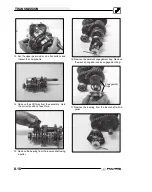
Remove Propshaft
REAR GEARCASE REMOVAL
CAUTION:
Serious injury may result if the machine
tips or falls. Be sure the machine is secure before
beginning this service procedure.
1. Place the ATV in park and set the parking brake.
2. Jack up the rear of the ATV and safely support the
ATV with jackstands.
3. Remove the two rear tires.
4. Remove the rear prop shaft from the rear
gearcase.
5. Remove the rear drive shafts. Refer to the “Rear
Drive Shaft Removal” section.
6. Remove the upper shock mounting bolt.
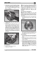
7. Remove the four mounting bolts and washers (A)
on the underside of the rear gearcase.
8. Remove the two mounting bolts and washers (B)
from the front of the rear gearcase.
9. Remove the five bolts, nuts, and washers, (C) and
(D), that hold the gearcase to the frame.
NOTE:
To remove the bottom bolts (C) from the rear
gearcase the lower control may have to be removed.
10. Pull the gearcase from the frame.
Содержание 600 Dragon SP
Страница 1: ...2004 SPORTSMAN 600 700 SERVICE MANUAL PN 9918803 ...
Страница 138: ...BODY STEERING SUSPENSION 5 16 NOTES ...
Страница 210: ...FINAL DRIVE 7 38 NOTES ...
Страница 293: ...ELECTRICAL 10 43 WIRING DIAGRAM HAND AND THUMB WARMERS WINCH HUNTER EDITION ...
Страница 294: ...ELECTRICAL 10 44 NOTES ...
Страница 295: ...ELECTRICAL WIRING DIAGRAM EARLY 2004 SPORTSMAN 600 700 BUILT BEFORE FEB 20 2003 Built Before February 20 2003 ...
Страница 297: ...ELECTRICAL WIRING DIAGRAM LATE 2004 SPORTSMAN 600 700 BUILT AFTER FEB 20 2003 Built After February 20 2003 ...
Страница 298: ...ELECTRICAL WIRING DIAGRAM LATE 2004 SPORTSMAN 600 700 BUILT AFTER FEB 20 2003 Built After February 20 2003 NOTES ...
Страница 299: ...ELECTRICAL WIRING DIAGRAM LATE 2004 SPORTSMAN 600 700 MODELS WITH FUEL GAUGE Models Equipped with Fuel Gauge ...
Страница 300: ...ELECTRICAL WIRING DIAGRAM LATE 2004 SPORTSMAN 600 700 MODELS WITH FUEL GAUGE NOTES ...
Страница 301: ...ELECTRICAL WIRING DIAGRAM 2004 SPORTSMAN 600 700 HUNTER EDT HAND WARM WINCH ...
Страница 307: ...Winch Switch Installation 10 34 Winch Wiring 10 35 Wiring Diagram Hand Thumb Warmer Winch 10 43 ...
Страница 308: ...PN 9918803 Printed in USA ...


