ENGINE
3.16
ENGINE INSTALLATION NOTES
After the engine is installed in the frame, review this
checklist and perform all steps that apply:
General Items
1. Install previously removed components using
new gaskets, seals, and fasteners where
applicable.
2. Perform regular checks on fluid levels, controls,
and all important areas on the vehicle as outlined
in the daily pre-ride inspection checklist (refer to
Chapter 2 or the Owner’s Manual).
PVT System
1. Adjust center distance of drive and driven clutch.
(Chapter 6)
2. Adjust clutch offset, alignment, and belt
deflection. (Chapter 6)
3. Clean clutch sheaves thoroughly and inspect inlet
and outlet ducts for proper routing and sealing.
(Chapter 6)
Transmission
1. Inspect transmission operation and adjust linkage
if necessary. Refer to Chapter 2 and Chapter 8.
Exhaust
1. Replace exhaust gaskets. Seal connections with
high temp silicone sealant.
2. Check to be sure all springs are in good condition.
Bleed Cooling System
NOTE:
This cooling system contains vent lines to
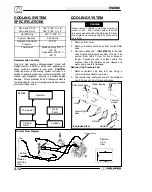
help purge trapped air during filling. Refer to Page
3.14 for hose routing. Bleeding generally should not
be necessary.
1. Remove radiator cap and slowly add coolant to
the bottom of filler neck.
2. Fill coolant reservoir tank to full mark.
3. Install radiator cap and gently squeeze coolant
hoses to force any trapped air out of system.
4. Again, remove radiator cap and slowly add
coolant to the bottom of fill neck if needed.
5. Start engine and observe coolant level in the
radiator.
Allow air to purge and top off as
necessary.
Reinstall radiator cap and bring
engine to operating temperature. After engine is
cool, check level in reservoir tank and add coolant
if necessary.
NOTE:
Should the reservoir tank become empty, it
will be necessary to refill at the radiator and repeat the
bleeding procedure.
Engine Break In Period
The break in period for a Polaris ATV engine is defined
as the first ten hours of operation, or the time it takes
to use two full tanks of gasoline. No single action on
your part is as important as a proper break in period.
Careful treatment of a new engine will result in more
efficient performance and longer life for the engine.
Perform the following procedures carefully.
Use only Polaris Premium 0--40W All Season
synthetic oil or equivalent. Never substitute or
mix oil brands. Serious engine damage and
voiding of warranty can result.
Do not operate at full throttle or high speeds for
extended periods during the first three hours of
use. Excessive heat can build up and cause
damage to close fitted engine parts.
CAUTION
1. Fill fuel tank with unleaded or leaded fuel which
has a minimum pump octane number of 87= (R+
M)/2.
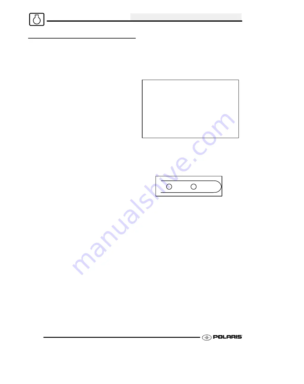
2. Check oil reservoir level indicated on dipstick.
Add oil if necessary.
SAFE
ADD 8 OZ
3. Drive slowly at first to gradually bring engine up to
operating temperature.
4. Vary throttle positions.
Do not operate at
sustained idle or sustained high speed.
5. Perform regular checks on fluid levels, controls
and all important areas on the vehicle.
6. Pull only light loads during initial break in.
7. Change break in oil and filter at 20 hours or 200
miles.
Содержание 600 Dragon SP
Страница 1: ...2004 SPORTSMAN 600 700 SERVICE MANUAL PN 9918803 ...
Страница 138: ...BODY STEERING SUSPENSION 5 16 NOTES ...
Страница 210: ...FINAL DRIVE 7 38 NOTES ...
Страница 293: ...ELECTRICAL 10 43 WIRING DIAGRAM HAND AND THUMB WARMERS WINCH HUNTER EDITION ...
Страница 294: ...ELECTRICAL 10 44 NOTES ...
Страница 295: ...ELECTRICAL WIRING DIAGRAM EARLY 2004 SPORTSMAN 600 700 BUILT BEFORE FEB 20 2003 Built Before February 20 2003 ...
Страница 297: ...ELECTRICAL WIRING DIAGRAM LATE 2004 SPORTSMAN 600 700 BUILT AFTER FEB 20 2003 Built After February 20 2003 ...
Страница 298: ...ELECTRICAL WIRING DIAGRAM LATE 2004 SPORTSMAN 600 700 BUILT AFTER FEB 20 2003 Built After February 20 2003 NOTES ...
Страница 299: ...ELECTRICAL WIRING DIAGRAM LATE 2004 SPORTSMAN 600 700 MODELS WITH FUEL GAUGE Models Equipped with Fuel Gauge ...
Страница 300: ...ELECTRICAL WIRING DIAGRAM LATE 2004 SPORTSMAN 600 700 MODELS WITH FUEL GAUGE NOTES ...
Страница 301: ...ELECTRICAL WIRING DIAGRAM 2004 SPORTSMAN 600 700 HUNTER EDT HAND WARM WINCH ...
Страница 307: ...Winch Switch Installation 10 34 Winch Wiring 10 35 Wiring Diagram Hand Thumb Warmer Winch 10 43 ...
Страница 308: ...PN 9918803 Printed in USA ...


