


BODY / STEERING / SUSPENSION
5.2
SPECIAL TOOLS
TOOL
DESCRIPTION
PART NUMBER
Ball Joint
Replacement Tool
2870871
Shock Spanner
Wrench
2870872
Shock Absorber
Spring
Compression Tool
2870623
Strut Rod Wrench
2871572
LH Strut Spring
Compressor
2871573
RH Strut Spring
Compressor
2871574
TORQUE SPECIFICATIONS
Front A-Arm Attaching Bolt.............30 ft. lbs. (41 Nm)
Front A-Arm Ball Joint Stud Nut.......25 ft. lbs. (35 Nm)
Handlebar Adjuster Block.....10-12 ft. lbs. (14-17 Nm)
Master Cylinder ................45-55 in. lbs. (5.2-6.3 Nm)
Rear Shock Bolt (upper)..................30 ft. lbs. (41 Nm)
Rear Shock Bolt (lower)..................30 ft. lbs. (41 Nm)
Rear Wheel Hub Nut...................100 ft. lbs. (136 Nm)
Wheel Nuts............................30 ft. lbs. (40.6 Nm)
Upper Stabilizer Support Nut...........17 ft. lbs. (24 Nm)
Upper Control Arm Mounting Bolt....35 ft. lbs. (48 Nm)
Lower Control Arm Mounting Bolt....30 ft. lbs. (41 Nm)
Upper Wheel Bearing Carrier Bolt...35 ft. lbs. (48 Nm)
Lower Wheel Bearing Carrier Bolt....30 ft. lbs. (41 Nm)
Strut Rod Retaining Nut (Top)..........15 ft. lbs. (21 Nm)
Strut Casting Pinch Bolt.................15 ft. lbs. (21 Nm)
Steering Post Nut...................0-12 ft. lbs. (14-17 Nm)
Steering Post Bushing Nuts......0-12 ft. lbs. (14-17
Nm)
Steering Post Bearing Retainer Nuts.0-12 ft. lbs.
(14-17 Nm
Tie Rod End Jam Nut............12-14 ft. lbs. (17-19 Nm)
Tie Rod End Castle Nut.........40-45 ft. lbs. (54-61 Nm)
Tie Rod End Attaching Bolt....25-30 ft. lbs. (35-41 Nm)
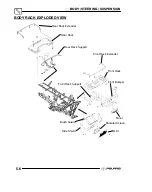
COVER/PANEL REMOVAL
To Remove:
Seat
Pull release lever at the rear of the
seat Lift and pull seat rearward,
disengaging seat from tabs at the
rear of the fuel tank
To Remove:
Side panels (See Page 5.3)
Remove Seat Disengage tabs at
front and rear and pull away
To Remove:
Headlight pod (See Page 5.8)
To Remove:
Front Cover
Remove Front rack,Disengage
cover and lift out
To Remove:
Rear Rack
Remove Seat, 2 bolts at rear of rack
and 2 bolts at front of rack
To Remove:
Rear Cab Assembly
Remove Seat
,
Rear rack,1 screw--
nut and washer at rear of inner left
footrest, 4 screws at bottom of left
rear mud flap, 1 screw, nut and
washer at rear of inner right
footrest, 4 screws at bottom of right
rear mud flap, 4 bolts and flat
washers from top of cab assembly
under seat, 2 screws at rear bottom
of cab assembly near tail light.
Disconnect taillight harness
To Remove:
Front rack
Remove 4 screws, lift off
To Remove:
Front Cab Assembly
Remove Seat, Side panels, 2 screws
at rear of cab at fuel tank mount
bracket, Front rack, Front bumper (4
screws), Front cover panel, 3 screws
from bottom left mud flap, 3 screws
from bottom right mud flap, 1 inner
screw from front cab to foot rest on
each side, 2 screws under front
panel, Remove fuel tank cap (reinstall
on tank after cab is removed)
To Remove:
Radiator Cover
Pull out slightly on the top of the
radiator screen, then pull out on the
bottom of the screen
Содержание 600 Dragon SP
Страница 1: ...2004 SPORTSMAN 600 700 SERVICE MANUAL PN 9918803 ...
Страница 138: ...BODY STEERING SUSPENSION 5 16 NOTES ...
Страница 210: ...FINAL DRIVE 7 38 NOTES ...
Страница 293: ...ELECTRICAL 10 43 WIRING DIAGRAM HAND AND THUMB WARMERS WINCH HUNTER EDITION ...
Страница 294: ...ELECTRICAL 10 44 NOTES ...
Страница 295: ...ELECTRICAL WIRING DIAGRAM EARLY 2004 SPORTSMAN 600 700 BUILT BEFORE FEB 20 2003 Built Before February 20 2003 ...
Страница 297: ...ELECTRICAL WIRING DIAGRAM LATE 2004 SPORTSMAN 600 700 BUILT AFTER FEB 20 2003 Built After February 20 2003 ...
Страница 298: ...ELECTRICAL WIRING DIAGRAM LATE 2004 SPORTSMAN 600 700 BUILT AFTER FEB 20 2003 Built After February 20 2003 NOTES ...
Страница 299: ...ELECTRICAL WIRING DIAGRAM LATE 2004 SPORTSMAN 600 700 MODELS WITH FUEL GAUGE Models Equipped with Fuel Gauge ...
Страница 300: ...ELECTRICAL WIRING DIAGRAM LATE 2004 SPORTSMAN 600 700 MODELS WITH FUEL GAUGE NOTES ...
Страница 301: ...ELECTRICAL WIRING DIAGRAM 2004 SPORTSMAN 600 700 HUNTER EDT HAND WARM WINCH ...
Страница 307: ...Winch Switch Installation 10 34 Winch Wiring 10 35 Wiring Diagram Hand Thumb Warmer Winch 10 43 ...
Страница 308: ...PN 9918803 Printed in USA ...


