


CLUTCH
6.19
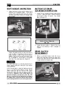
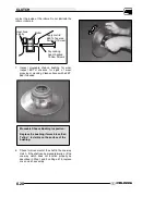
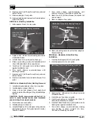
Move Freely
2. When rotated clockwise, the outer sheave should
lock to the shaft and inner sheave without
slipping.
Lock to Shaft and Outer Sheave
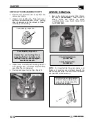
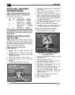
3. Remove driven clutch from the transmission input
shaft. Do not attempt disassembly of the driven
clutch from the outside snap ring. The driven
clutch must be disassembled from the helix side
or the one-way clutch seals may be damaged.
Do not disassemble from this side
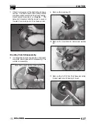
4. Place the driven assembly into the clutch holder.
Push helix inward. Remove snap ring, washer,
helix, and spring. NOTE: The spring is a
compression spring only and has no torsional
wind.
NOTE:
Rotating the moveable sheave so that the
rollers are not in contact with either helix ramp
surfaces will lessen the effort needed to push the helix
inward.
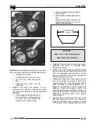
5. Remove spring seat washer and inspect for wear
or damage. Replace if worn.
6. Inspect surface of rollers for flat spots and wear.
Rollers must rotate freely on pins without
excessive clearance. Check the roller pin and
roller bore for wear and replace if necessary.
Rollers
ROLLER PIN DISASSEMBLY
New roller retaining bolts have a dry locking agent
applied to the threads. Before attempting to remove
the roller pins, heat the threaded area lightly with a
propane torch.
Wear heat resistant gloves during
this procedure.
Use a high quality hexagonal
wrench in good condition to avoid screw damage. A
small amount of valve grinding compound can be
applied to the tip of the hex wrench to ensure a tight
fit. Always use new bolts if they are removed for
inspection. Apply Loctite
t
680 retaining compound
sparingly to the tapered head portion of the roller
retaining screws. Do not allow locking agent to
Содержание 600 Dragon SP
Страница 1: ...2004 SPORTSMAN 600 700 SERVICE MANUAL PN 9918803 ...
Страница 138: ...BODY STEERING SUSPENSION 5 16 NOTES ...
Страница 210: ...FINAL DRIVE 7 38 NOTES ...
Страница 293: ...ELECTRICAL 10 43 WIRING DIAGRAM HAND AND THUMB WARMERS WINCH HUNTER EDITION ...
Страница 294: ...ELECTRICAL 10 44 NOTES ...
Страница 295: ...ELECTRICAL WIRING DIAGRAM EARLY 2004 SPORTSMAN 600 700 BUILT BEFORE FEB 20 2003 Built Before February 20 2003 ...
Страница 297: ...ELECTRICAL WIRING DIAGRAM LATE 2004 SPORTSMAN 600 700 BUILT AFTER FEB 20 2003 Built After February 20 2003 ...
Страница 298: ...ELECTRICAL WIRING DIAGRAM LATE 2004 SPORTSMAN 600 700 BUILT AFTER FEB 20 2003 Built After February 20 2003 NOTES ...
Страница 299: ...ELECTRICAL WIRING DIAGRAM LATE 2004 SPORTSMAN 600 700 MODELS WITH FUEL GAUGE Models Equipped with Fuel Gauge ...
Страница 300: ...ELECTRICAL WIRING DIAGRAM LATE 2004 SPORTSMAN 600 700 MODELS WITH FUEL GAUGE NOTES ...
Страница 301: ...ELECTRICAL WIRING DIAGRAM 2004 SPORTSMAN 600 700 HUNTER EDT HAND WARM WINCH ...
Страница 307: ...Winch Switch Installation 10 34 Winch Wiring 10 35 Wiring Diagram Hand Thumb Warmer Winch 10 43 ...
Страница 308: ...PN 9918803 Printed in USA ...


