ELECTRICAL
10.16
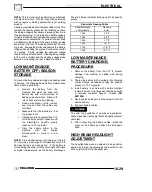
FAN CONTROL SWITCH
OPERATION TEST
1. Place switch in a water bath and submerse it to
the base of the threads. Do not allow threads to
contact container or inaccurate reading will result.
2. Heat the coolant slowly and monitor the
temperature with a thermometer or Fluke
t
meter
pyrometer.
The switch should be closed
(conductive) at the “ON” temperature indicated in
the chart, and stay conductive until the “OFF”
temperature is reached.
REFER TO PARTS MANUAL FOR FAN
SWITCH APPLICATION
Fan Switch
Operation
Continuity
(On)
No Continuity
(Off)
Temperature
180
°
F (82
°
C)
±
3
°
F
149
°
F (65
°
C)
±
8
°
F
ELECTRONIC THROTTLE
CONTROL (ETC) SWITCH
The Electronic Throttle Control (ETC) system is
designed to stop the engine of an ATV in the event of
a mechanical problem with the throttle mechanism.
The ETC switch is mounted independently of the
throttle actuator lever inside the throttle block
assembly. This is a
normally closed
switch, and is
held in the open position (contacts are separated (as
shown below) by throttle cable tension. The contacts
are “open” during normal operation regardless of
throttle lever position. In the event of a mechanical
problem in the throttle mechanism (cable tension is
lost), the switch contacts close, connecting the CDI
black wire to ground, which prevents ignition spark.
This is the same as turning the key or engine stop
switch “OFF”.
Test the ETC switch at the harness connector.
NOTE:
Adjust throttle cable freeplay (ETC switch) and make
sure throttle mechanism is functioning properly before
testing the switch. Refer to Maintenance Chapter 2
for cable adjustment procedure
.
ETC OPERATION TEST
Remove throttle block cover by carefully releasing all
tabs around edge of cover.
Place transmission in neutral and apply parking
brake.
Start engine and open throttle lever slightly until
engine RPM is just above idle speed.
Hold throttle cable with fingers at point “A” as shown
below and release throttle lever. If the ETC system is
functioning properly, the engine will lose spark and
stop.
Switch contacts are
open
during normal operation
A
ETC switch contacts are
closed
in a fault condition
(throttle cable slack).
Electronic Throttle Control (ETC) Switch
(Composite Throttle Housing)
Brn
Blk
Brn
CDI UNIT
Содержание 600 Dragon SP
Страница 1: ...2004 SPORTSMAN 600 700 SERVICE MANUAL PN 9918803 ...
Страница 138: ...BODY STEERING SUSPENSION 5 16 NOTES ...
Страница 210: ...FINAL DRIVE 7 38 NOTES ...
Страница 293: ...ELECTRICAL 10 43 WIRING DIAGRAM HAND AND THUMB WARMERS WINCH HUNTER EDITION ...
Страница 294: ...ELECTRICAL 10 44 NOTES ...
Страница 295: ...ELECTRICAL WIRING DIAGRAM EARLY 2004 SPORTSMAN 600 700 BUILT BEFORE FEB 20 2003 Built Before February 20 2003 ...
Страница 297: ...ELECTRICAL WIRING DIAGRAM LATE 2004 SPORTSMAN 600 700 BUILT AFTER FEB 20 2003 Built After February 20 2003 ...
Страница 298: ...ELECTRICAL WIRING DIAGRAM LATE 2004 SPORTSMAN 600 700 BUILT AFTER FEB 20 2003 Built After February 20 2003 NOTES ...
Страница 299: ...ELECTRICAL WIRING DIAGRAM LATE 2004 SPORTSMAN 600 700 MODELS WITH FUEL GAUGE Models Equipped with Fuel Gauge ...
Страница 300: ...ELECTRICAL WIRING DIAGRAM LATE 2004 SPORTSMAN 600 700 MODELS WITH FUEL GAUGE NOTES ...
Страница 301: ...ELECTRICAL WIRING DIAGRAM 2004 SPORTSMAN 600 700 HUNTER EDT HAND WARM WINCH ...
Страница 307: ...Winch Switch Installation 10 34 Winch Wiring 10 35 Wiring Diagram Hand Thumb Warmer Winch 10 43 ...
Страница 308: ...PN 9918803 Printed in USA ...


