


FINAL DRIVE
7.32
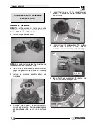
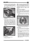
5. Refit CV joint on interconnecting shaft by tapping
with a plastic hammer on the joint housing. Take
care not to damage threads on the outboard CV
joint. The joint is fully assembled when the snap
ring is located in the groove on the
interconnecting shaft.
Tap joint onto shaft
6. Install and tighten large boot clamp with boot
clamp pliers.
7. Remove any excess grease from the CV joint
external surfaces and position joint boot over
housing, making sure boot is seated in groove.
Position clamp over boot end and make sure
clamp tabs are located in slots.
NOTE:
Before
tightening boot clamp on inboard joint, make sure
any air pressure which may have built up in joint
boot has been released. The air should be
released after the plunging joint has been
centered properly. Tighten boot clamp using boot
clamp pliers.
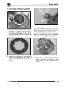
Open snap ring and pull
CV joint away from shaft
Boot Replacement
1. Remove CV joint from end of shaft.
2. Remove boot from shaft.
NOTE:
When replacing a damaged boot, check the
grease for contamination by rubbing it between two
fingers. A gritty feeling indicates contamination. If
the grease is not contaminated, the boot can be
replaced without cleaning the CV joint. Use the
recommended
amount
of
grease
for
boot
replacement
only (see below). Proceed to Boot
Installation.
CV Joint Cleaning / Replacement
NOTE:
Shiny areas in ball tracks and on the cage
spheres are normal. Do not replace CV joints because
parts have polished surfaces. Replace CV joint only
if components are cracked, broken, worn or otherwise
unserviceable.
3. Thoroughly clean and dry the CV joint and inspect
ball tracks and cages for wear, cracks or other
damage.
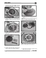
4. Add the recommended amount of grease for
CV
joint cleaning
to the joint as shown below. Be
sure grease penetrates all parts of the joint.
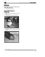
Boot Installation
5. Fit joint boot and clamps on interconnecting shaft.
Make sure small end of boot is fully seated in
groove.
6. Position small clamp over small end of boot. Be
sure it is seated all the way around in the clamp
recess on the boot.
7. Tighten small boot clamp using boot clamp pliers.
8. Fill boot with grease supplied from boot service kit
and spread evenly inside CV joint. Be sure to use
only the Constant Velocity Joint grease supplied
with boot service kit.
NOTE:
IF CV JOINT WAS
CLEANED, add the recommended amount of
grease to the joint
in addition
to the grease pack
supplied with boot kit.
Содержание 600 Dragon SP
Страница 1: ...2004 SPORTSMAN 600 700 SERVICE MANUAL PN 9918803 ...
Страница 138: ...BODY STEERING SUSPENSION 5 16 NOTES ...
Страница 210: ...FINAL DRIVE 7 38 NOTES ...
Страница 293: ...ELECTRICAL 10 43 WIRING DIAGRAM HAND AND THUMB WARMERS WINCH HUNTER EDITION ...
Страница 294: ...ELECTRICAL 10 44 NOTES ...
Страница 295: ...ELECTRICAL WIRING DIAGRAM EARLY 2004 SPORTSMAN 600 700 BUILT BEFORE FEB 20 2003 Built Before February 20 2003 ...
Страница 297: ...ELECTRICAL WIRING DIAGRAM LATE 2004 SPORTSMAN 600 700 BUILT AFTER FEB 20 2003 Built After February 20 2003 ...
Страница 298: ...ELECTRICAL WIRING DIAGRAM LATE 2004 SPORTSMAN 600 700 BUILT AFTER FEB 20 2003 Built After February 20 2003 NOTES ...
Страница 299: ...ELECTRICAL WIRING DIAGRAM LATE 2004 SPORTSMAN 600 700 MODELS WITH FUEL GAUGE Models Equipped with Fuel Gauge ...
Страница 300: ...ELECTRICAL WIRING DIAGRAM LATE 2004 SPORTSMAN 600 700 MODELS WITH FUEL GAUGE NOTES ...
Страница 301: ...ELECTRICAL WIRING DIAGRAM 2004 SPORTSMAN 600 700 HUNTER EDT HAND WARM WINCH ...
Страница 307: ...Winch Switch Installation 10 34 Winch Wiring 10 35 Wiring Diagram Hand Thumb Warmer Winch 10 43 ...
Страница 308: ...PN 9918803 Printed in USA ...


