0507347110/160114/B SHIELD fire safety solutions (5k1)
| INSTALLATION | EN - 23
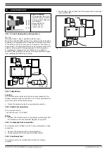
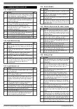
13.7 Solenoid valve
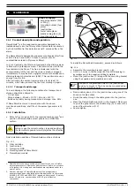
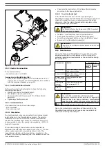
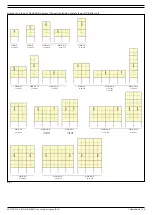
13.8 FlameShield
13.9 System control panel SCP
13.10 Final
The entire system including the ShieldControl panel must be
tested periodically in accordance with the national fire
protection association requirements or the authorities having
local jurisdiction.
The indicated maintenance intervals can vary depending on the
specific working and ambient conditions. Therefore it is
recommended to perform the first general maintenance check
three months after commissioning and determine the future
frequency based on the state of the system after this period. In
any case the complete system must be checked at least once a
year.
•
Refer to the separate system components about method and
frequency of maintenance. Maintenance activities have been
summarized in the maintenance calendar below.
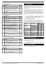
14.1 Maintenance calendar
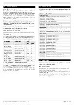
The maintenance activities in the table below indicated by [*]
can be carried out by the user; other activities are strictly
reserved for well trained and authorized service personnel.
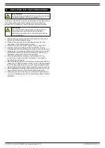
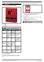
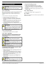
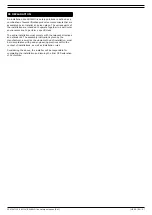
The post-fire procedure is strictly reserved to skilled and
authorised service engineers.
•
Carry out the post-fire procedure as written in paragraph
18.2 on page 25.
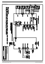
Refer to electrical diagram on page 29.
#
Check
OK
1.
Is the 3/2 solenoid valve mounted between
compressed air reducer (CAR kit) and filter?
2.
Is the solenoid electrically and pneumatically
correctly wired? When the solenoid is
disconnected from power, the air of the
compressed air tanks of the filter system should
be released.
3.
Is the solenoid functionally tested after a fire
test alarm in the complete system set up?
#
Check
OK
1.
Are FlameShield modules undamaged?
2.
Is the correct number of FlameShield modules
being installed?
3.
Are the FlameShield modules placed at the
correct position?
4.
Are the FlameShield modules pushed back to
the middle stop of the mounting bracket to
secure a 10° downwards release angle?
5.
Are all nuts and bolts well tightened?
6.
Are the cables tension free, well guided and
fixed by the cable glands?
7.
Are the cable glands well tightened?
8.
Is the internal wiring/electrical activation
checked by measuring resistance over the
internal heating device of the FlameShield with
a current less than 5 mA? The resistance must
be 2 ohm.
9.
Are, in combination with ShieldControl 5k1, the
EOL resistor-diodes of 5k1 placed in each
junction box and the FlameShield connected to
output 2, 3 or 4?
#
Check
OK
1.
Is the system control panel SCP correctly
connected to the ShieldControl panel and
peripheral equipment?
2.
Is the system control panel SCP functionally
tested on a test alarm and performed expected
actions (fan stops, sliding valves close, 3/2
solenoid opens)?
#
Check
OK
1.
After all functional testing, reset all detectors
and panels. When no alarm signals are visible,
connect the FlameShield modules. Make sure
that ShieldControl is on
RUN
.
14
MAINTENANCE
Frequency
Component
* Ref.
par.
page
Regularly,
depending on
intensity of use
Heat detectors
* 6.5
Spark detectors
* 7.5
Smoke detector
* 8.5
Whenever dirty
ShieldControl panel * 5.5
Every 6 months
Sliding valves
At least every 12
months
FlameShield
Every year
ShieldControl panel
Every 4 years
ShieldControl panel
Every 10 years
FlameShield
15
POST-FIRE PROCEDURE
16
ELECTRICAL DIAGRAM
Содержание Shield 5k1
Страница 1: ...www plymovent com EN Fire safety solutions EN Installation and user manual shield 5k1...
Страница 30: ...SHIELD fire safety solutions 5k1 ELECTRICAL DIAGRAM 29 Electrical diagram 900010G0026 0 22 05 2014...
Страница 31: ......
Страница 32: ...www plymovent com 0507347110 160114 B SHIELD 5k1 EN...

